- Arc Welding Function

Содержание
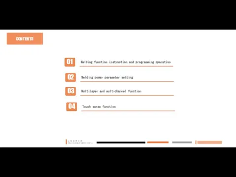
- 2. CONTENTS
- 3. PART 01 Welding Function Instruction and Programming Operation
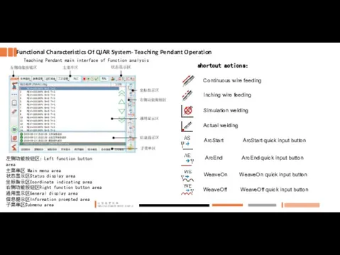
- 4. Teaching Pendant main interface of Function analysis Functional Characteristics Of QJAR System- Teaching Pendant Operation shortcut
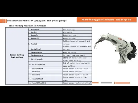
- 5. Basic welding function instruction Functional Characteristics Of QJAR System- Basic process package Robot welding process software
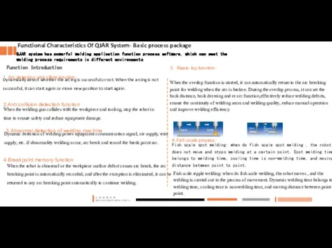
- 6. Functional Characteristics Of QJAR System- Basic process package Dynamically detect whether the arcing is successful or
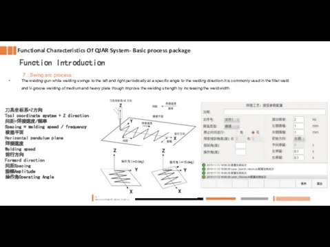
- 7. Functional Characteristics Of QJAR System- Basic process package 7.:Swing arc process: The welding gun while welding
- 8. Basic programming operation QJAR System Programming For Arc Welding Program Teaching programming steps 1. Turn the
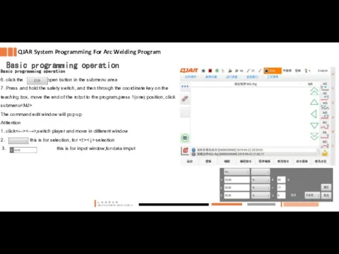
- 9. Basic programming operation 6. click the open button in the submenu area 7. Press and hold
- 10. 4. After inputting the corresponding parameters as required, press confirm. The command line is displayed in
- 11. Click - - , and the following window will pop up. After entering the corresponding parameters
- 12. Click to open the window on the right (Note: for digital communication while welding, in the
- 13. Repeat above similar steps above. Input all program points and instructions. Through the above steps, the
- 14. Example of large pose arc editing program Example of plane arc editing program QJAR System Programming
- 15. 1、MJV=40% B=100 2、MJV=40% B=100 3、ArcStart(1,0.0) 4、MLV=10mm/s B=100 5、 SetWorkMode low spatter 6、MLV=10mm/s B=100 7、 ArcIVC(100.0,10.1) 8、
- 16. PART 02 Arc welding power source communication and application setting
- 17. Analog / digital welding power management: Communication And Application Of Arc Welding Power Source Support Aotai
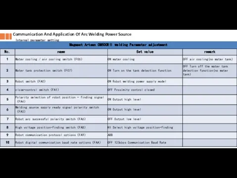
- 18. Communication And Application Of Arc Welding Power Source Internal parameter setting
- 19. PART 03 Multilayer and multipass arc welding function
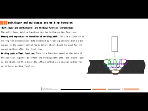
- 20. Multilayer and multipass arc welding function Multilayer and multichannel arc welding function introduction The multi-layer welding
- 21. Multilayer and multipass function arc welding function Multilayer and Multichannel Parameter Setting 1、Click - - to
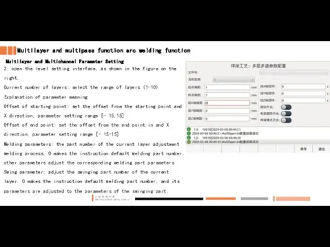
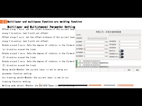
- 22. Multilayer and multipass function arc welding function Multilayer and Multichannel Parameter Setting 2. open the level
- 23. Multilayer and multipass function arc welding function Multilayer and Multichannel Parameter Setting Offset along Y axis:
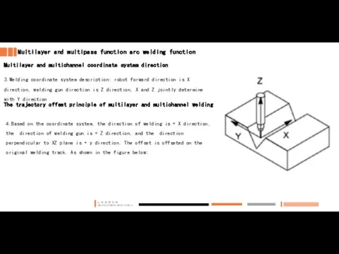
- 24. Multilayer and multipass function arc welding function Multilayer and multichannel coordinate system direction 3.Welding coordinate system
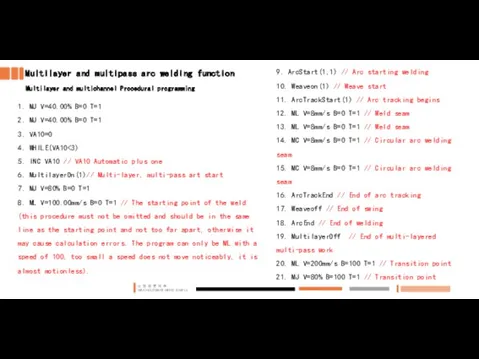
- 25. Multilayer and multipass arc welding function Multilayer and multichannel Procedural programming 1. MJ V=40.00% B=0 T=1
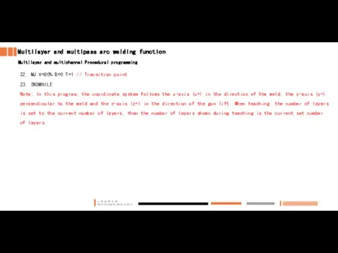
- 26. Multilayer and multipass arc welding function Multilayer and multichannel Procedural programming 22. MJ V=80% B=0 T=1
- 27. PART 04 Touch Sense Function PART 04
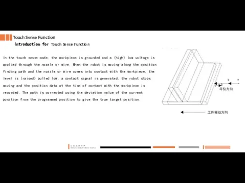
- 28. Touch Sense Function Introduction for Touch Sense Function In the touch sense mode, the workpiece is
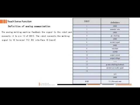
- 29. Touch Sense Function Definition of analog communication The analog welding machine feedback the signal to the
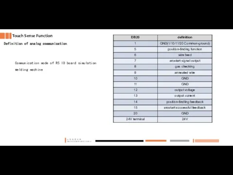
- 30. Touch Sense Function Definition of analog communication Communication mode of R5 IO board simulation welding machine
- 31. Touch Sense Function Parameter setting Open path : - - -
- 32. Touch Sense function Parameter setting It needs to create a user coordinate system, user calibration to
- 33. Touch Sense Function Parameter setting Sensor signal:From low to high by default Coordinate system number: enter
- 34. Touch Sense Function 1D Function details Examples of procedures SearchStart(1)(P1) ML MLSearch +x pos[1] SearchENd TouchOffset(P1)
- 35. Touch Sense Function 2D Function details Examples of procedures SearchStart(1) //finding position start ML Tool =1
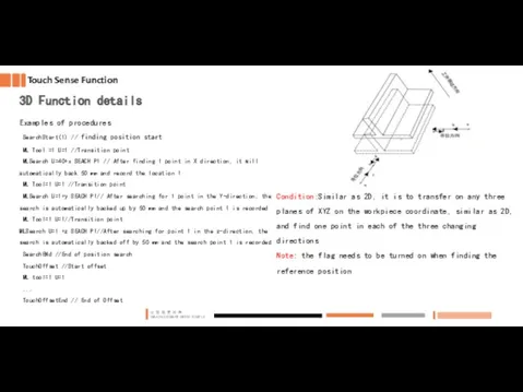
- 36. Touch Sense Function 3D Function details Examples of procedures SearchStart(1) // finding position start ML Tool
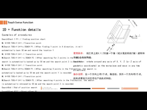
- 37. Touch Sense Function 2D + Function details Examples of procedures SearchStart 1 P1 // finding position
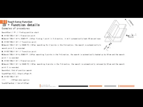
- 38. Touch Sense Function 2D + Function details Examples of procedures SearchStart 1 P1 // finding position
- 39. Touch Sense Function 3D + Function details Examples of procedures SearchStart 1 P1 // Bit search
- 40. Touch Sense Function 3D + Function details Conditions of use: Rotate or translate anywhere around X,Y,Z
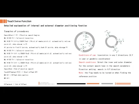
- 41. Touch Sense Function Detailed explanation of internal and external diameter positioning function Examples of procedures SearchStart
- 43. Скачать презентацию
CONTENTS
CONTENTS

PART 01
Welding Function Instruction and Programming Operation
PART 01
Welding Function Instruction and Programming Operation
Teaching Pendant main interface of Function analysis
Functional Characteristics Of QJAR
Functional Characteristics Of QJAR
Basic welding function instruction
Functional Characteristics Of QJAR System- Basic process package
Robot
Basic welding function instruction
Functional Characteristics Of QJAR System- Basic process package
Robot
Functional Characteristics Of QJAR System- Basic process package
Dynamically detect whether the
Functional Characteristics Of QJAR System- Basic process package
Dynamically detect whether the
Functional Characteristics Of QJAR System- Basic process package
7.:Swing arc process:
The welding
Functional Characteristics Of QJAR System- Basic process package
7.:Swing arc process:
The welding
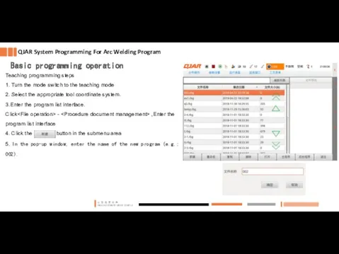
Basic programming operation
QJAR System Programming For Arc Welding Program
Teaching programming steps
1.
QJAR System Programming For Arc Welding Program
Teaching programming steps
1.
Basic programming operation
6. click the open button in the submenu area
7.
Basic programming operation
6. click the open button in the submenu area
7.
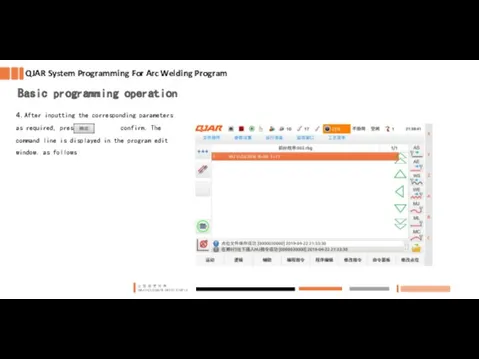
4. After inputting the corresponding parameters as required, press confirm. The
4. After inputting the corresponding parameters as required, press confirm. The

Click < programming instruction > - -
Click < programming instruction > -
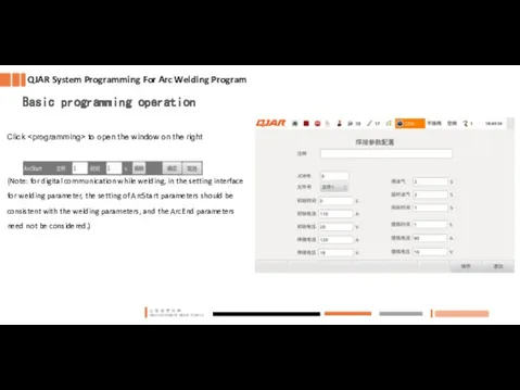
Click to open the window on the right
(Note: for digital
Click
(Note: for digital
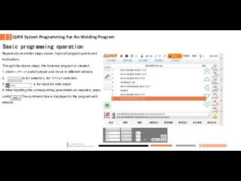
Repeat above similar steps above. Input all program points and instructions.
Through
Repeat above similar steps above. Input all program points and instructions.
Through
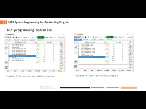
Example of large pose arc editing program
Example of plane arc
Example of plane arc
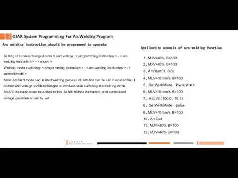
1、MJV=40% B=100
2、MJV=40% B=100
3、ArcStart(1,0.0)
4、MLV=10mm/s B=100
5、 SetWorkMode low spatter
6、MLV=10mm/s B=100
7、 ArcIVC(100.0,10.1)
8、 SetWorkMode pulse
9、MLV=10mm/s
1、MJV=40% B=100
2、MJV=40% B=100
3、ArcStart(1,0.0)
4、MLV=10mm/s B=100
5、 SetWorkMode low spatter
6、MLV=10mm/s B=100
7、 ArcIVC(100.0,10.1)
8、 SetWorkMode pulse
9、MLV=10mm/s

PART 02
Arc welding power source communication and application setting
PART 02
Arc welding power source communication and application setting
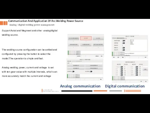
Analog / digital welding power management:
Communication And Application Of Arc Welding
Communication And Application Of Arc Welding
Communication And Application Of Arc Welding Power Source
Internal parameter setting
Communication And Application Of Arc Welding Power Source
Internal parameter setting

PART 03
Multilayer and multipass arc welding function
PART 03
Multilayer and multipass arc welding function
Multilayer and multipass arc welding function
Multilayer and multichannel arc welding function
Multilayer and multipass arc welding function
Multilayer and multichannel arc welding function

Multilayer and multipass function arc welding function
Multilayer and Multichannel Parameter Setting
1、Click
Multilayer and multipass function arc welding function
Multilayer and Multichannel Parameter Setting
1、Click
Multilayer and multipass function arc welding function
Multilayer and Multichannel Parameter Setting
2.
Multilayer and multipass function arc welding function
Multilayer and Multichannel Parameter Setting
2.
Multilayer and multipass function arc welding function
Multilayer and Multichannel Parameter Setting
Offset
Multilayer and multipass function arc welding function
Multilayer and Multichannel Parameter Setting
Offset
Multilayer and multipass function arc welding function
Multilayer and multichannel coordinate
Multilayer and multipass function arc welding function
Multilayer and multichannel coordinate
Multilayer and multipass arc welding function
Multilayer and multichannel Procedural programming
1.
Multilayer and multipass arc welding function
Multilayer and multichannel Procedural programming
1.
Multilayer and multipass arc welding function
Multilayer and multichannel Procedural programming
22.
Multilayer and multipass arc welding function
Multilayer and multichannel Procedural programming
22.
PART 04
Touch Sense Function
PART 04
PART 04
Touch Sense Function
PART 04
Touch Sense Function
Introduction for Touch Sense Function
In the touch
Touch Sense Function
Introduction for Touch Sense Function
In the touch
Touch Sense Function
Definition of analog communication
The analog welding machine feedback
Touch Sense Function
Definition of analog communication
The analog welding machine feedback
Touch Sense Function
Definition of analog communication
Communication mode of R5 IO
Touch Sense Function
Definition of analog communication
Communication mode of R5 IO
Touch Sense Function
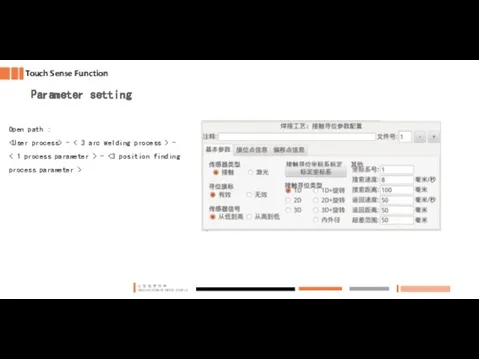
Parameter setting
Open path :
- < 3
Touch Sense Function
Parameter setting
Open path :
Touch Sense function
Parameter setting
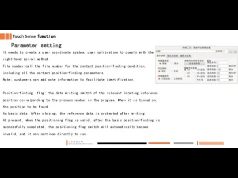
It needs to create a user coordinate system,
Touch Sense function
Parameter setting
It needs to create a user coordinate system,

Touch Sense Function
Parameter setting
Sensor signal:From low to high by default
Coordinate system
Touch Sense Function
Parameter setting
Sensor signal:From low to high by default
Coordinate system
Touch Sense Function
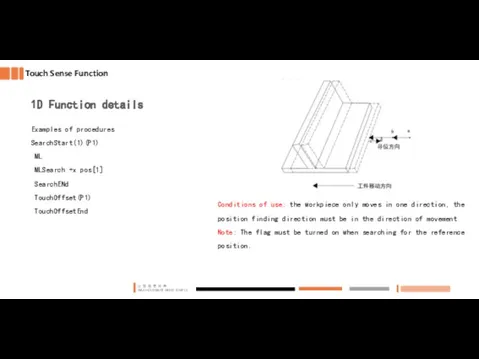
1D Function details
Examples of procedures
SearchStart(1)(P1)
ML
MLSearch +x
Touch Sense Function
1D Function details
Examples of procedures
SearchStart(1)(P1)
ML
MLSearch +x
Touch Sense Function
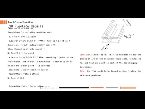
2D Function details
Examples of procedures
SearchStart(1) //finding position start
Touch Sense Function
2D Function details
Examples of procedures
SearchStart(1) //finding position start
Touch Sense Function
3D Function details
Examples of procedures
SearchStart(1) // finding
Touch Sense Function
3D Function details
Examples of procedures
SearchStart(1) // finding
Touch Sense Function
2D + Function details
Examples of procedures
SearchStart 1 P1
Touch Sense Function
2D + Function details
Examples of procedures
SearchStart 1 P1
Touch Sense Function
2D + Function details
Examples of procedures
SearchStart 1 P1
Touch Sense Function
2D + Function details
Examples of procedures
SearchStart 1 P1

Touch Sense Function
3D + Function details
Examples of procedures
SearchStart 1 P1
Touch Sense Function
3D + Function details
Examples of procedures
SearchStart 1 P1

Touch Sense Function
3D + Function details
Conditions of use: Rotate or translate
Touch Sense Function
3D + Function details
Conditions of use: Rotate or translate
Touch Sense Function
Detailed explanation of internal and external diameter positioning function
Examples
Touch Sense Function
Detailed explanation of internal and external diameter positioning function
Examples
 Газовая сварка стали
 Применение гомогенизации при производстве молока и молочных продуктов. Цель, механизм, режимы, способы
 20111020_syuzhet
 Урок 2
 Стиральные машины
 Системы автоматической блокировки
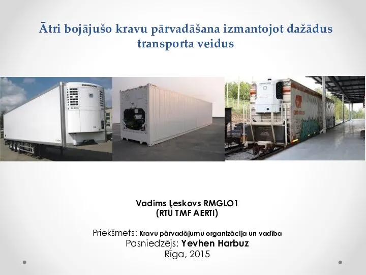 Ātri bojājušo kravu pārvadāšana izmantojot dažādus transporta veidus
 м6 — копия
 Самомассаж
 Классификация строительных конструкций. Принципы формирования строительных конструкций
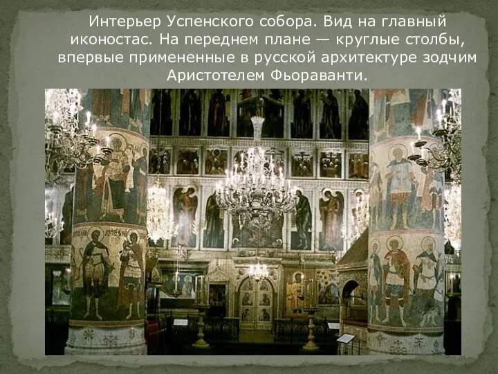 Интерьер Успенского собора
 Остапенко Проект fyrty
 Поп-арт Гламур. Тенденции моды
 Необходимость применения оптоэлектроники для человека
 Арматура. Арматуралардың түрлері
 Чудеса Иисуса Христа в пределах Десятиградия (Мф. 15, 29 38; Мк. 7, 31 8, 9)
 Технологическая оснастка обсадных колонн
 Гетероперехід. Емісійна модель різкого p-n гетеропереходу
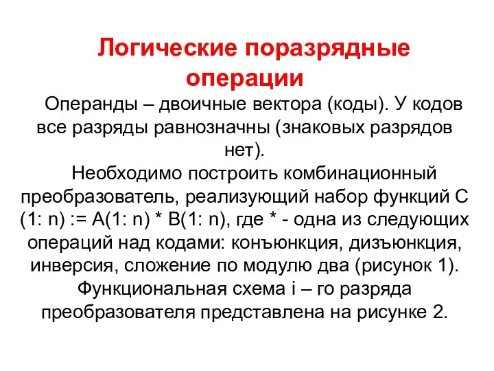 Логические поразрядные операции
 Рукоположение достойных. Библия
 Освещение жилого помещения. Урок технологии (6 класс)
 Характеристика до образу Галина баба
 10_klass_KBZh_s_sovremennoy_srede_obitania_1
 Монтаж кабельной муфты
 Любимый питомец. Руся
 Контактная точечная сварка
 Языковая осень в КФМЛ
 Интеллектуальная игра по мотивам шоу Где логика