- Motorola solutions learning. Network application interface (NAI). Radio management (RM)

Содержание
- 2. SECTIONS 1. Introduction: High Level Overview / Demo Network Application Interface (NAI) Radio Management (RM) Technical:
- 3. INTRODUCTION
- 4. Mobility Notifications Presence Notifications ARS Messages Data (ADK) Router/Switch Site 2 Router/Switch Site 1 NAI &
- 5. NETWORK APPLICATION INTERFACE (NAI)
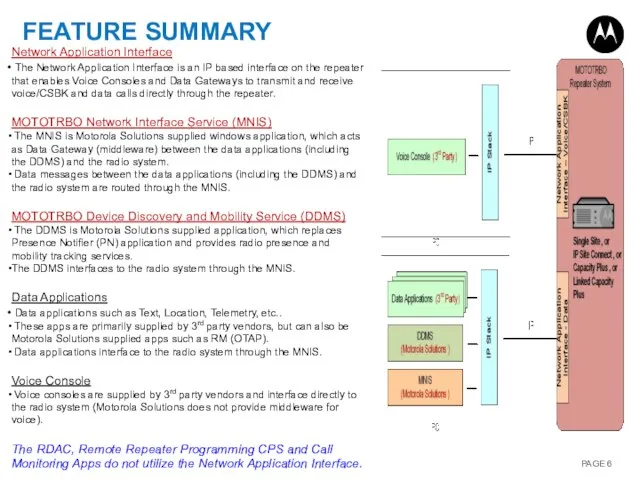
- 6. FEATURE SUMMARY Network Application Interface The Network Application Interface is an IP based interface on the
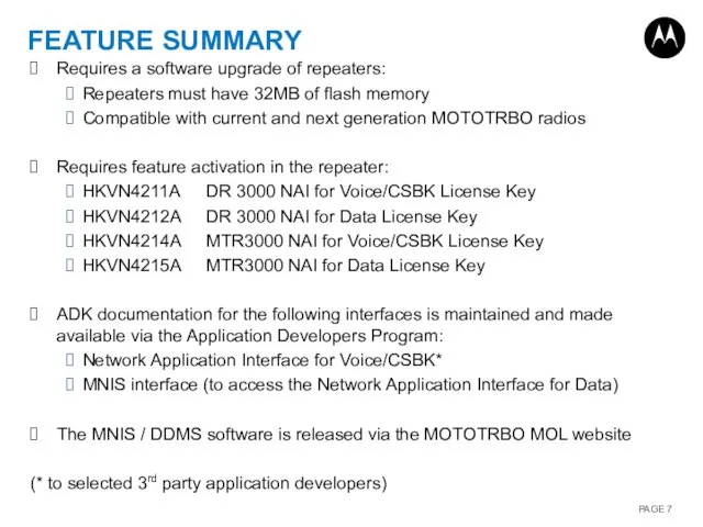
- 7. FEATURE SUMMARY Requires a software upgrade of repeaters: Repeaters must have 32MB of flash memory Compatible
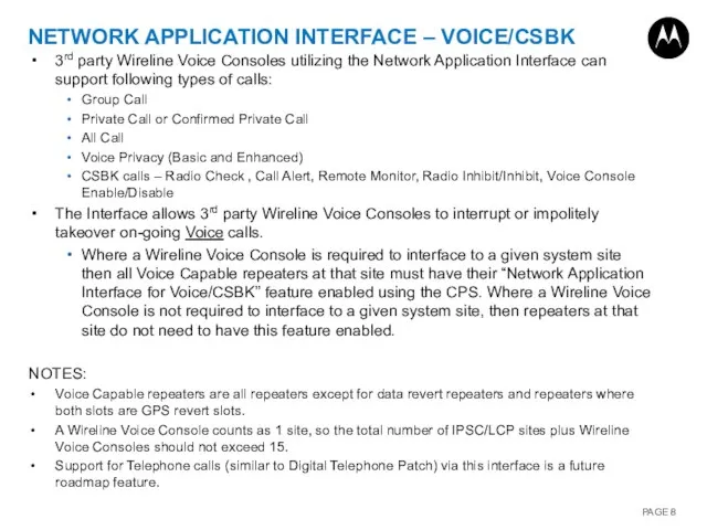
- 8. NETWORK APPLICATION INTERFACE – VOICE/CSBK 3rd party Wireline Voice Consoles utilizing the Network Application Interface can
- 9. NETWORK APPLICATION INTERFACE – VOICE/CSBK A Wireline Voice Console is required to interface directly to the
- 10. NETWORK APPLICATION INTERFACE – DATA The Network Application Interface for Data is an internal interface between
- 11. MNIS OVERVIEW The MNIS is supported by Windows XP, Windows 7, Windows Server 2003 & 2008
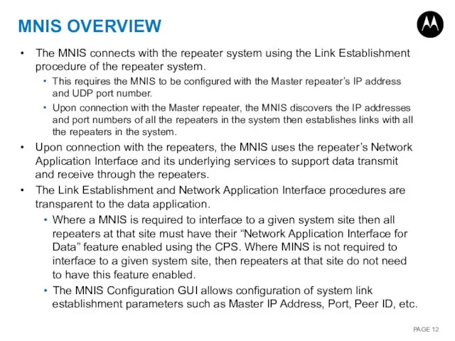
- 12. MNIS OVERVIEW The MNIS connects with the repeater system using the Link Establishment procedure of the
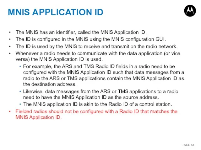
- 13. MNIS APPLICATION ID The MNIS has an identifier, called the MNIS Application ID. The ID is
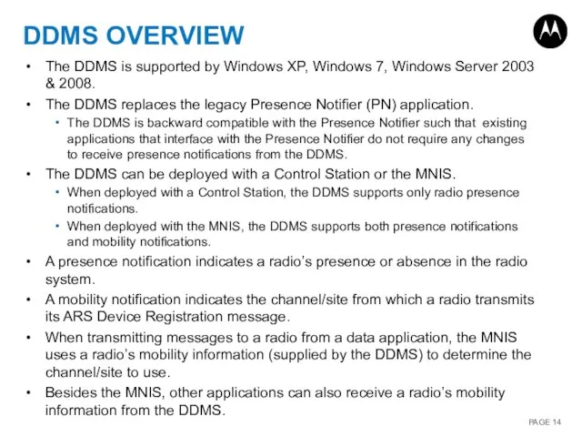
- 14. DDMS OVERVIEW The DDMS is supported by Windows XP, Windows 7, Windows Server 2003 & 2008.
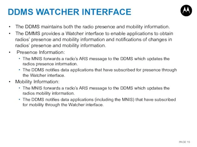
- 15. DDMS WATCHER INTERFACE The DDMS maintains both the radio presence and mobility information. The DMMS provides
- 16. RADIO MANAGEMENT (RM) All MOTOTRBO radios can be managed and programmed / read using a wired
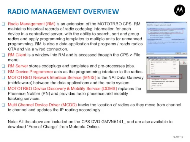
- 17. RADIO MANAGEMENT OVERVIEW Radio Management (RM) is an extension of the MOTOTRBO CPS. RM maintains historical
- 18. RADIO MANAGEMENT (RM) SOFTWARE LICENSES The Radio Management (RM) Server can store and manage up to
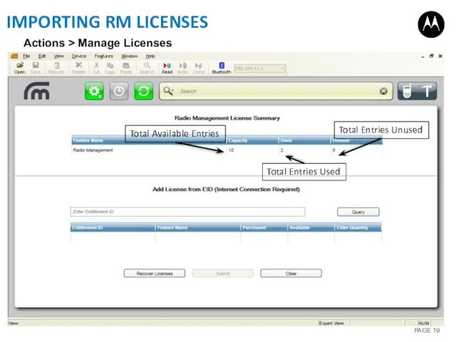
- 19. IMPORTING RM LICENSES Total Available Entries Total Entries Used Total Entries Unused Actions > Manage Licenses
- 20. TECHNICAL
- 21. NETWORK APPLICATION INTERFACE (NAI)
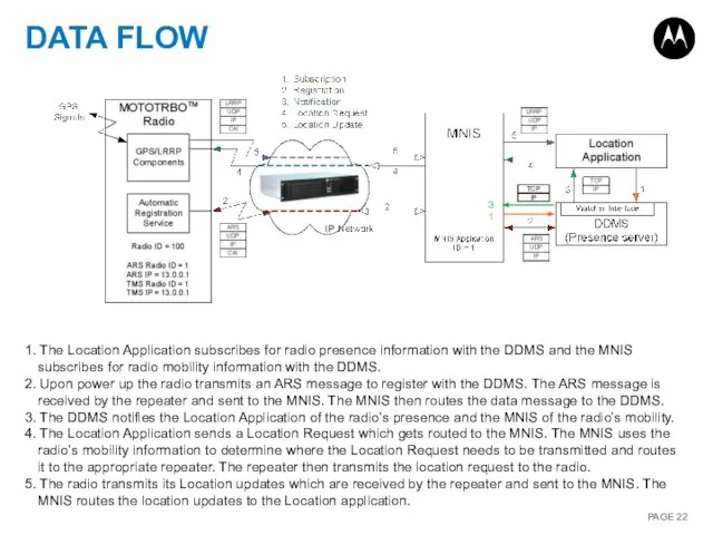
- 22. DATA FLOW 1. The Location Application subscribes for radio presence information with the DDMS and the
- 23. SYSTEM CONFIGURATIONS The MNIS supports the following MOTOTRBO Digital system topologies: Single Site Conventional, IP Site
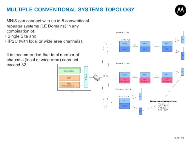
- 24. MULTIPLE CONVENTIONAL SYSTEMS TOPOLOGY MNIS can connect with up to 8 conventional repeater systems (LE Domains)
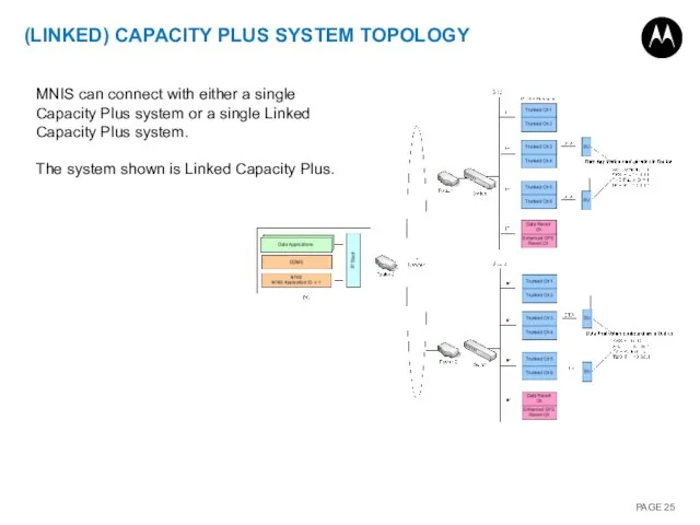
- 25. (LINKED) CAPACITY PLUS SYSTEM TOPOLOGY MNIS can connect with either a single Capacity Plus system or
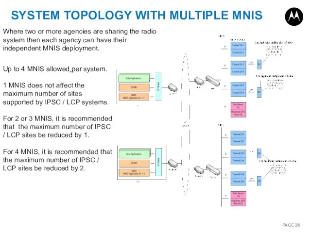
- 26. SYSTEM TOPOLOGY WITH MULTIPLE MNIS Where two or more agencies are sharing the radio system then
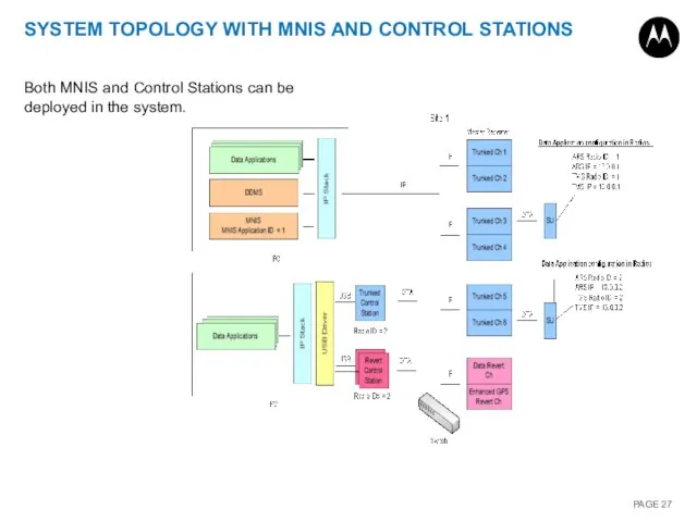
- 27. SYSTEM TOPOLOGY WITH MNIS AND CONTROL STATIONS Both MNIS and Control Stations can be deployed in
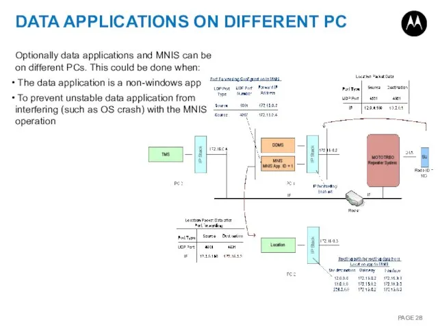
- 28. DATA APPLICATIONS ON DIFFERENT PC Optionally data applications and MNIS can be on different PCs. This
- 29. OTAP WITH MNIS DEPLOYMENT The considerations for deploying the Radio Management application with MNIS are the
- 30. DEPLOYMENT WITH OTHER APPS MNIS, DDMS, RDAC, Remote Repeater Programming and Radio Management can be deployed
- 31. RADIO CONFIGURATION Configure ARS Radio ID Configure TMS Radio ID Notes: The ARS and TMS Radio
- 32. REPEATER CONFIGURATION 1 Purchase Network Application Interface Data feature Note: Typically the feature will need to
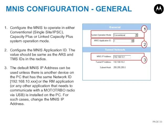
- 33. MNIS CONFIGURATION - GENERAL 1 2 3 Configure the MNIS to operate in either Conventional (Single
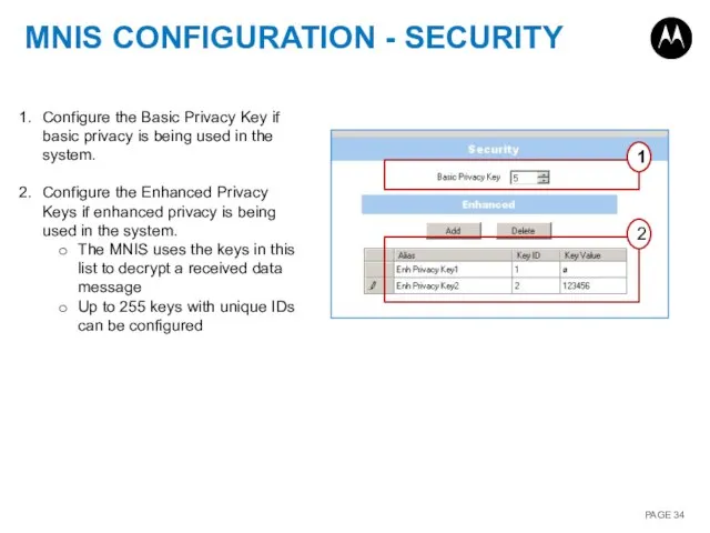
- 34. MNIS CONFIGURATION - SECURITY 1 2 Configure the Basic Privacy Key if basic privacy is being
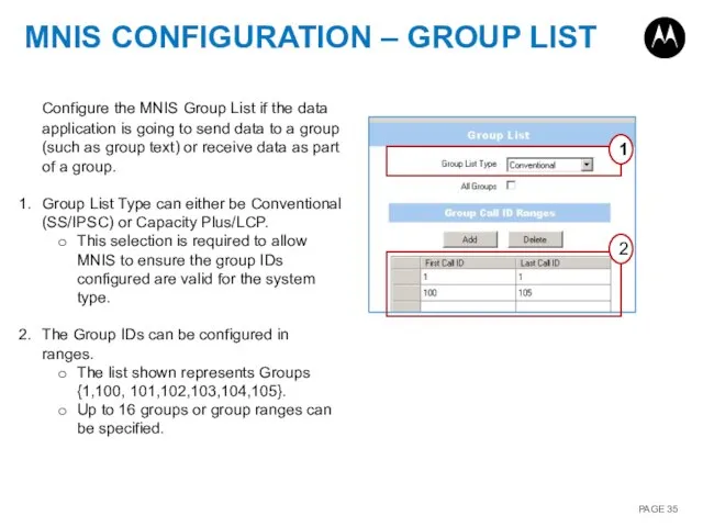
- 35. MNIS CONFIGURATION – GROUP LIST 1 2 Configure the MNIS Group List if the data application
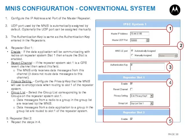
- 36. MNIS CONFIGURATION - CONVENTIONAL SYSTEM 1 4 5 2 3 Configure the IP Address and Port
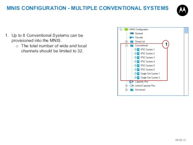
- 37. MNIS CONFIGURATION - MULTIPLE CONVENTIONAL SYSTEMS Up to 8 Conventional Systems can be provisioned into the
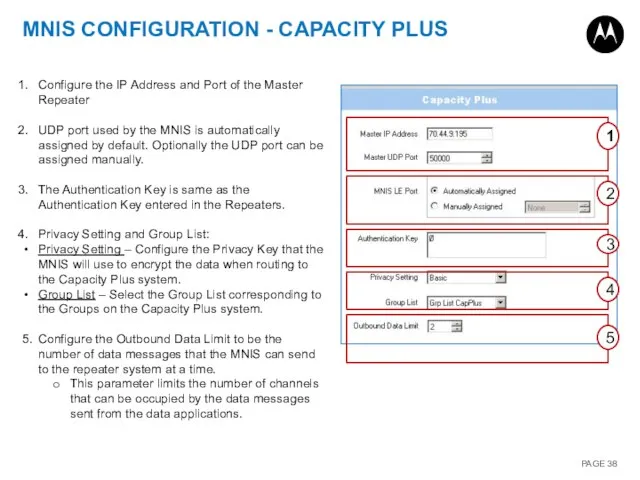
- 38. MNIS CONFIGURATION - CAPACITY PLUS 1 2 3 4 5 Configure the IP Address and Port
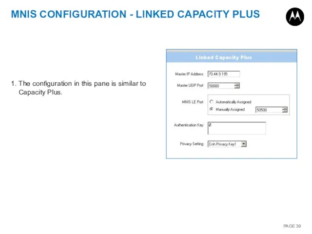
- 39. MNIS CONFIGURATION - LINKED CAPACITY PLUS 1. The configuration in this pane is similar to Capacity
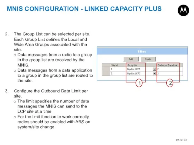
- 40. MNIS CONFIGURATION - LINKED CAPACITY PLUS 1 2 The Group List can be selected per site.
- 41. MNIS CONTROLS 1 2 The Green Color indicates that the configuration is an active configuration, which
- 42. DDMS CONFIGURATION The default configurations for the DDMS in most cased do not need to be
- 43. RADIO MANAGEMENT (RM) All MOTOTRBO radios can be managed and programmed / read using a wired
- 44. USB OTA USB RADIO MANAGEMENT OVERVIEW Presence Notifications Data ARS Messages Data Applications (Radio Management) Presence
- 45. RADIO MANAGEMENT CONFIGURATION EXAMPLE RM Client RM Server RM Device Prog IP: 127.0.0.1 (localhost) Port: 8675
- 46. USB Driver CONTROL STATION / RADIO CONFIGURATION EXAMPLE 12.0.0.51 13.0.0.51 192.168.10.1 12.0.0.51 192.168.10.1 13.0.0.51 192.168.10.2 Network
- 47. RM CLIENT SCREEN Actions Schedule Job Radio View Job View Search Field Add Group Templates Actions:
- 48. RECOMMENDED RM SERVER POPULATION METHOD The recommended RM Server population method includes a ‘Wire Read’ of
- 49. RECOMMENDED TEMPLATE MANAGEMENT METHOD A Template consists of that codeplug data which is common to all
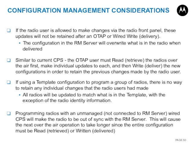
- 50. CONFIGURATION MANAGEMENT CONSIDERATIONS If the radio user is allowed to make changes via the radio front
- 51. RM allows scheduling of multiple radio configurations to be delivered over the air unattended. RM will
- 52. Delivery with Switchover - radio will apply the changes after delivery Use when changing non-critical parameters:
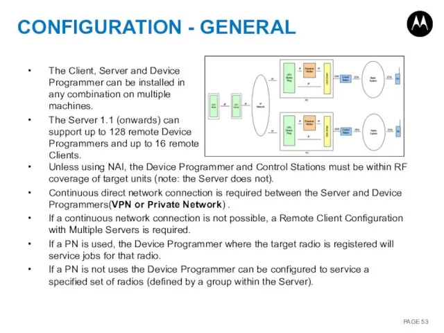
- 53. CONFIGURATION - GENERAL Unless using NAI, the Device Programmer and Control Stations must be within RF
- 54. UNIQUE RADIO ID When using a centralized RM Server to communicate to multiple systems with remote
- 55. RM DEVICE PROGRAMMER - AUTOMATICALLY PROCESS JOBS (WIRED MODE) RM Device Programmer in Wired mode: Check
- 56. MANAGE OPTIONS Manage: Templates Voice Announcements Language Packs Enhanced Privacy Keys OTAP Keys RAS Keys Firmware
- 57. MANAGE TEMPLATES Radio View Radio Button Import New Radios Edit Radio Alias / ID / CIA
- 58. MANAGE VOICE ANNOUNCEMENTS To view and manage VA (Voice Announcement) files in RM Server go to:
- 59. MANAGE LANGUAGE PACKS To view and manage Language Pack files in RM Server go to: Actions
- 60. MANAGE KEYS To view and manage Secure keys in RM Server go to one of the
- 61. MANAGE FIRMWARE To view and manage Firmware Packages in RM Server go to: Actions > Manage
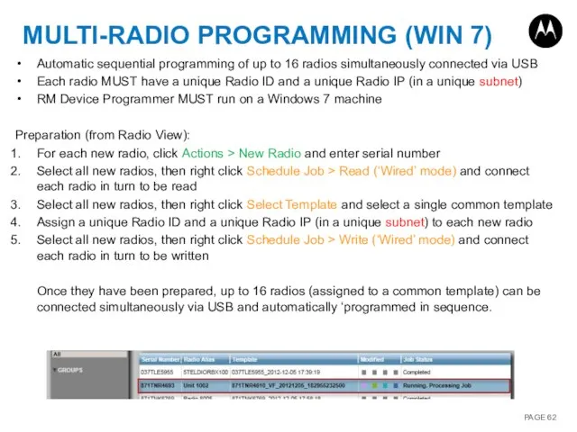
- 62. MULTI-RADIO PROGRAMMING (WIN 7) Automatic sequential programming of up to 16 radios simultaneously connected via USB
- 64. Скачать презентацию
SECTIONS
1. Introduction:
High Level Overview / Demo
Network Application Interface (NAI)
Radio Management (RM)
Technical:
Network Application
SECTIONS
1. Introduction:
High Level Overview / Demo
Network Application Interface (NAI)
Radio Management (RM)
Technical:
Network Application

INTRODUCTION
INTRODUCTION
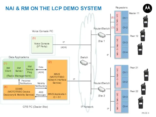
Mobility Notifications
Presence Notifications
ARS Messages
Data
(ADK)
Router/Switch
Site 2
Router/Switch
Site 1
NAI & RM ON THE LCP
Mobility Notifications
Presence Notifications
ARS Messages
Data
(ADK)
Router/Switch
Site 2
Router/Switch
Site 1
NAI & RM ON THE LCP

NETWORK APPLICATION INTERFACE (NAI)
NETWORK APPLICATION INTERFACE (NAI)
FEATURE SUMMARY
Network Application Interface
The Network Application Interface is an IP
FEATURE SUMMARY
Network Application Interface
The Network Application Interface is an IP
FEATURE SUMMARY
Requires a software upgrade of repeaters:
Repeaters must have 32MB of
FEATURE SUMMARY
Requires a software upgrade of repeaters:
Repeaters must have 32MB of
NETWORK APPLICATION INTERFACE – VOICE/CSBK
3rd party Wireline Voice Consoles utilizing the
NETWORK APPLICATION INTERFACE – VOICE/CSBK
3rd party Wireline Voice Consoles utilizing the
NETWORK APPLICATION INTERFACE – VOICE/CSBK
A Wireline Voice Console is required to
NETWORK APPLICATION INTERFACE – VOICE/CSBK
A Wireline Voice Console is required to
NETWORK APPLICATION INTERFACE – DATA
The Network Application Interface for Data is
NETWORK APPLICATION INTERFACE – DATA
The Network Application Interface for Data is
MNIS OVERVIEW
The MNIS is supported by Windows XP, Windows 7, Windows
MNIS OVERVIEW
The MNIS is supported by Windows XP, Windows 7, Windows
MNIS OVERVIEW
The MNIS connects with the repeater system using the Link
MNIS OVERVIEW
The MNIS connects with the repeater system using the Link
MNIS APPLICATION ID
The MNIS has an identifier, called the MNIS Application
MNIS APPLICATION ID
The MNIS has an identifier, called the MNIS Application
DDMS OVERVIEW
The DDMS is supported by Windows XP, Windows 7, Windows
DDMS OVERVIEW
The DDMS is supported by Windows XP, Windows 7, Windows
DDMS WATCHER INTERFACE
The DDMS maintains both the radio presence and mobility
DDMS WATCHER INTERFACE
The DDMS maintains both the radio presence and mobility
RADIO MANAGEMENT (RM)
All MOTOTRBO radios can be managed and programmed /
RADIO MANAGEMENT (RM)
All MOTOTRBO radios can be managed and programmed /
RADIO MANAGEMENT OVERVIEW
Radio Management (RM) is an extension of the MOTOTRBO
RADIO MANAGEMENT OVERVIEW
Radio Management (RM) is an extension of the MOTOTRBO
RADIO MANAGEMENT (RM) SOFTWARE LICENSES
The Radio Management (RM) Server can store
RADIO MANAGEMENT (RM) SOFTWARE LICENSES
The Radio Management (RM) Server can store
IMPORTING RM LICENSES
Total Available Entries
Total Entries Used
Total Entries Unused
Actions >
IMPORTING RM LICENSES
Total Available Entries
Total Entries Used
Total Entries Unused
Actions >

TECHNICAL
TECHNICAL
NETWORK APPLICATION INTERFACE (NAI)
NETWORK APPLICATION INTERFACE (NAI)
DATA FLOW
1. The Location Application subscribes for radio presence information with
DATA FLOW
1. The Location Application subscribes for radio presence information with
SYSTEM CONFIGURATIONS
The MNIS supports the following MOTOTRBO Digital system topologies: Single
SYSTEM CONFIGURATIONS
The MNIS supports the following MOTOTRBO Digital system topologies: Single
MULTIPLE CONVENTIONAL SYSTEMS TOPOLOGY
MNIS can connect with up to 8 conventional
MULTIPLE CONVENTIONAL SYSTEMS TOPOLOGY
MNIS can connect with up to 8 conventional
(LINKED) CAPACITY PLUS SYSTEM TOPOLOGY
MNIS can connect with either a single
(LINKED) CAPACITY PLUS SYSTEM TOPOLOGY
MNIS can connect with either a single
SYSTEM TOPOLOGY WITH MULTIPLE MNIS
Where two or more agencies are sharing
SYSTEM TOPOLOGY WITH MULTIPLE MNIS
Where two or more agencies are sharing
SYSTEM TOPOLOGY WITH MNIS AND CONTROL STATIONS
Both MNIS and Control Stations
SYSTEM TOPOLOGY WITH MNIS AND CONTROL STATIONS
Both MNIS and Control Stations
DATA APPLICATIONS ON DIFFERENT PC
Optionally data applications and MNIS can be
DATA APPLICATIONS ON DIFFERENT PC
Optionally data applications and MNIS can be
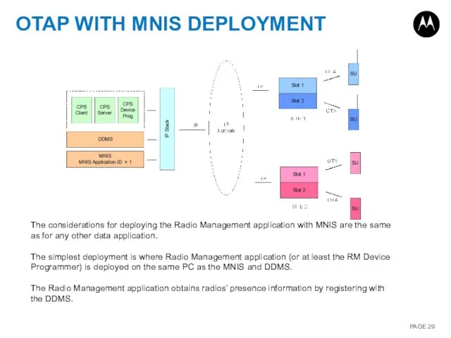
OTAP WITH MNIS DEPLOYMENT
The considerations for deploying the Radio Management application
OTAP WITH MNIS DEPLOYMENT
The considerations for deploying the Radio Management application
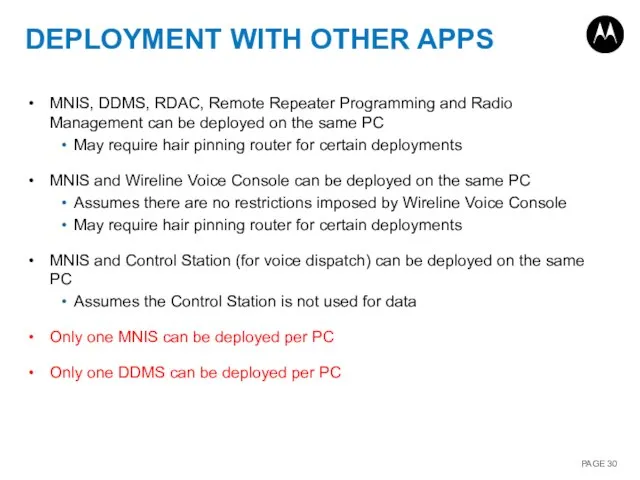
DEPLOYMENT WITH OTHER APPS
MNIS, DDMS, RDAC, Remote Repeater Programming and Radio
DEPLOYMENT WITH OTHER APPS
MNIS, DDMS, RDAC, Remote Repeater Programming and Radio
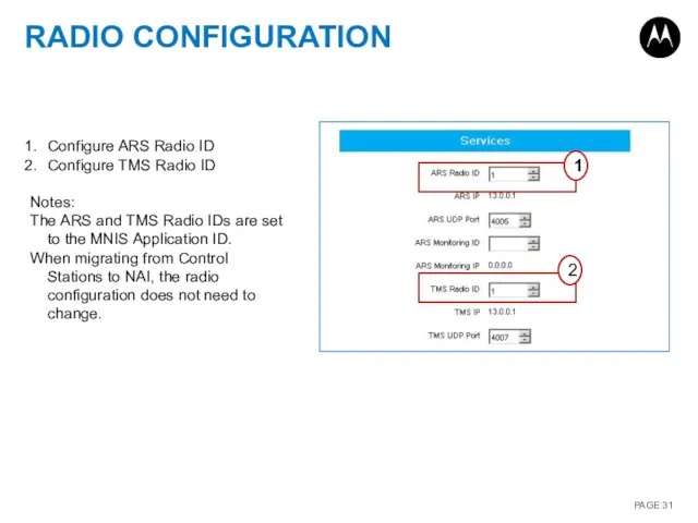
RADIO CONFIGURATION
Configure ARS Radio ID
Configure TMS Radio ID
Notes:
The ARS and TMS
RADIO CONFIGURATION
Configure ARS Radio ID
Configure TMS Radio ID
Notes:
The ARS and TMS
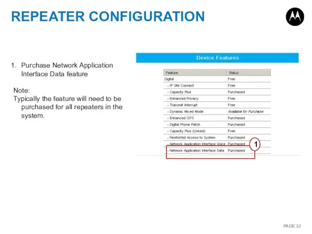
REPEATER CONFIGURATION
1
Purchase Network Application Interface Data feature
Note:
Typically the feature will
REPEATER CONFIGURATION
1
Purchase Network Application Interface Data feature
Note:
Typically the feature will
MNIS CONFIGURATION - GENERAL
1
2
3
Configure the MNIS to operate in either Conventional
MNIS CONFIGURATION - GENERAL
1
2
3
Configure the MNIS to operate in either Conventional
MNIS CONFIGURATION - SECURITY
1
2
Configure the Basic Privacy Key if basic privacy
MNIS CONFIGURATION - SECURITY
1
2
Configure the Basic Privacy Key if basic privacy
MNIS CONFIGURATION – GROUP LIST
1
2
Configure the MNIS Group List if the
MNIS CONFIGURATION – GROUP LIST
1
2
Configure the MNIS Group List if the
MNIS CONFIGURATION - CONVENTIONAL SYSTEM
1
4
5
2
3
Configure the IP Address and Port of
MNIS CONFIGURATION - CONVENTIONAL SYSTEM
1
4
5
2
3
Configure the IP Address and Port of
MNIS CONFIGURATION - MULTIPLE CONVENTIONAL SYSTEMS
Up to 8 Conventional Systems can
MNIS CONFIGURATION - MULTIPLE CONVENTIONAL SYSTEMS
Up to 8 Conventional Systems can
MNIS CONFIGURATION - CAPACITY PLUS
1
2
3
4
5
Configure the IP Address and Port of
MNIS CONFIGURATION - CAPACITY PLUS
1
2
3
4
5
Configure the IP Address and Port of
MNIS CONFIGURATION - LINKED CAPACITY PLUS
1. The configuration in this pane is
MNIS CONFIGURATION - LINKED CAPACITY PLUS
1. The configuration in this pane is
MNIS CONFIGURATION - LINKED CAPACITY PLUS
1
2
The Group List can be selected
MNIS CONFIGURATION - LINKED CAPACITY PLUS
1
2
The Group List can be selected
MNIS CONTROLS
1
2
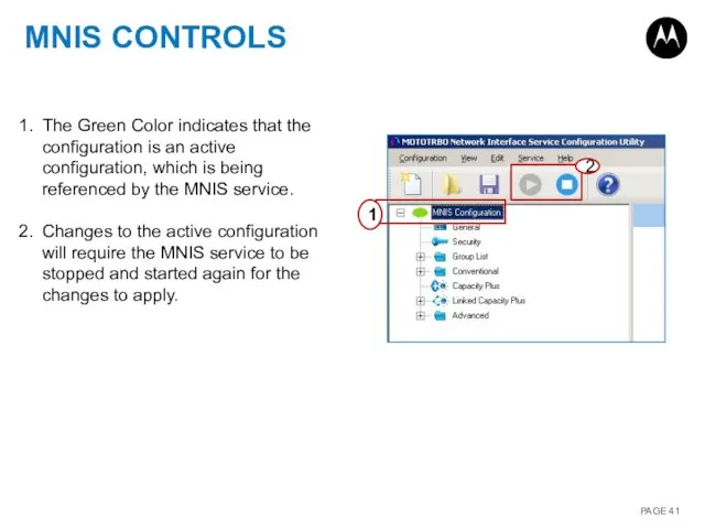
The Green Color indicates that the configuration is an active
MNIS CONTROLS
1
2
The Green Color indicates that the configuration is an active
DDMS CONFIGURATION
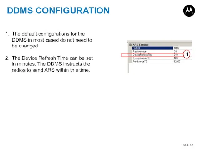
The default configurations for the DDMS in most cased do
DDMS CONFIGURATION
The default configurations for the DDMS in most cased do

RADIO MANAGEMENT (RM)
All MOTOTRBO radios can be managed and programmed /
RADIO MANAGEMENT (RM)
All MOTOTRBO radios can be managed and programmed /
USB
OTA
USB
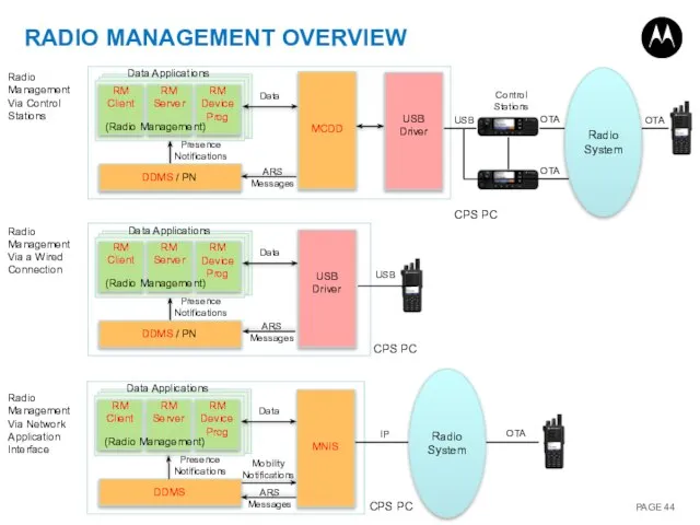
RADIO MANAGEMENT OVERVIEW
Presence Notifications
Data
ARS Messages
Data Applications
(Radio Management)
Presence Notifications
Data
ARS Messages
Data Applications
(Radio Management)
OTA
Control
USB
OTA
USB
RADIO MANAGEMENT OVERVIEW
Presence Notifications
Data
ARS Messages
Data Applications
(Radio Management)
Presence Notifications
Data
ARS Messages
Data Applications
(Radio Management)
OTA
Control
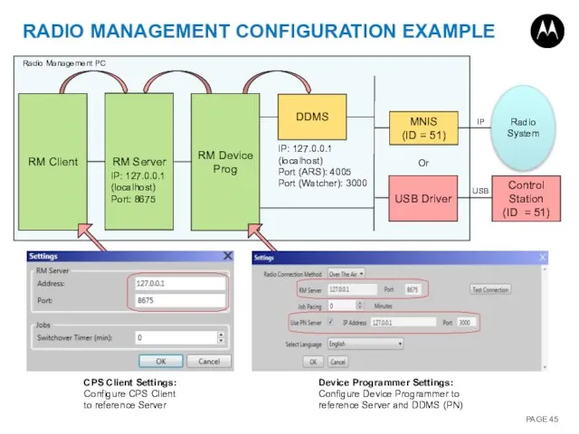
RADIO MANAGEMENT CONFIGURATION EXAMPLE
RM Client
RM Server
RM Device Prog
IP: 127.0.0.1 (localhost)
Port: 8675
IP:
RADIO MANAGEMENT CONFIGURATION EXAMPLE
RM Client
RM Server
RM Device Prog
IP: 127.0.0.1 (localhost)
Port: 8675
IP:
USB Driver
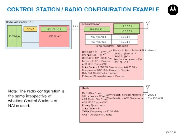
CONTROL STATION / RADIO CONFIGURATION EXAMPLE
12.0.0.51
13.0.0.51
192.168.10.1
12.0.0.51
192.168.10.1
13.0.0.51
192.168.10.2
Network Address Translation
Radio ID =
USB Driver
CONTROL STATION / RADIO CONFIGURATION EXAMPLE
12.0.0.51
13.0.0.51
192.168.10.1
12.0.0.51
192.168.10.1
13.0.0.51
192.168.10.2
Network Address Translation
Radio ID =
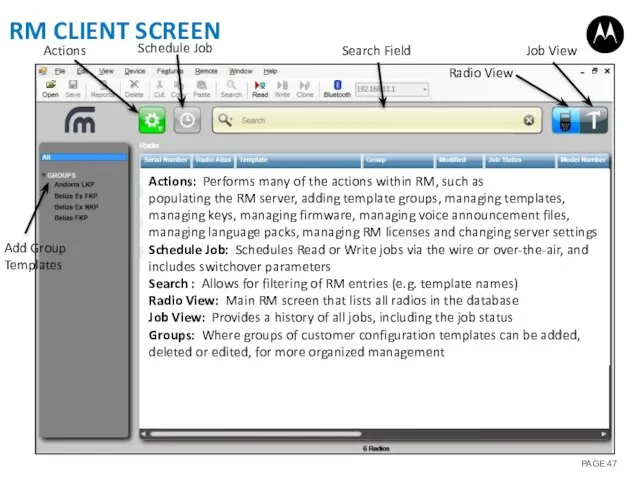
RM CLIENT SCREEN
Actions
Schedule Job
Radio View
Job View
Search Field
Add Group Templates
Actions: Performs many
RM CLIENT SCREEN
Actions
Schedule Job
Radio View
Job View
Search Field
Add Group Templates
Actions: Performs many
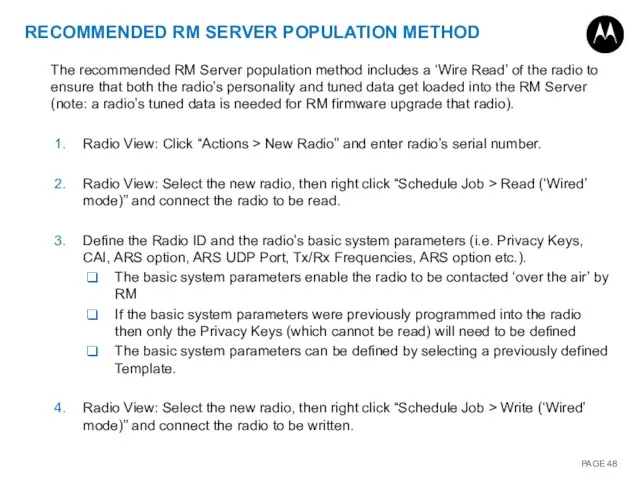
RECOMMENDED RM SERVER POPULATION METHOD
The recommended RM Server population method includes
RECOMMENDED RM SERVER POPULATION METHOD
The recommended RM Server population method includes
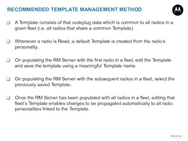
RECOMMENDED TEMPLATE MANAGEMENT METHOD
A Template consists of that codeplug data which
RECOMMENDED TEMPLATE MANAGEMENT METHOD
A Template consists of that codeplug data which
CONFIGURATION MANAGEMENT CONSIDERATIONS
If the radio user is allowed to make changes
CONFIGURATION MANAGEMENT CONSIDERATIONS
If the radio user is allowed to make changes
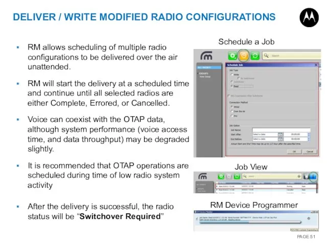
RM allows scheduling of multiple radio configurations to be delivered over
RM allows scheduling of multiple radio configurations to be delivered over
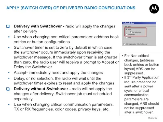
Delivery with Switchover - radio will apply the changes after delivery
Delivery with Switchover - radio will apply the changes after delivery
CONFIGURATION - GENERAL
Unless using NAI, the Device Programmer and Control Stations
CONFIGURATION - GENERAL
Unless using NAI, the Device Programmer and Control Stations
UNIQUE RADIO ID
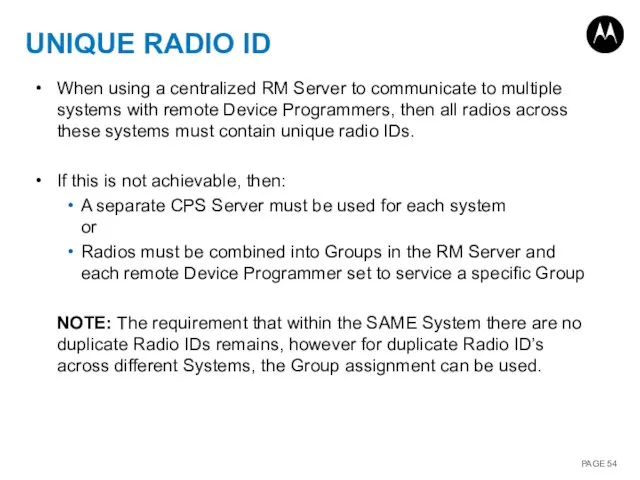
When using a centralized RM Server to communicate to
UNIQUE RADIO ID
When using a centralized RM Server to communicate to
RM DEVICE PROGRAMMER
- AUTOMATICALLY PROCESS JOBS (WIRED MODE)
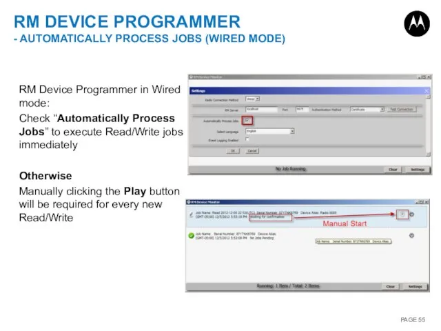
RM Device Programmer in
RM DEVICE PROGRAMMER
- AUTOMATICALLY PROCESS JOBS (WIRED MODE)
RM Device Programmer in
MANAGE OPTIONS
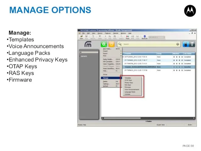
Manage:
Templates
Voice Announcements
Language Packs
Enhanced Privacy Keys
OTAP Keys
RAS Keys
Firmware
MANAGE OPTIONS
Manage:
Templates
Voice Announcements
Language Packs
Enhanced Privacy Keys
OTAP Keys
RAS Keys
Firmware
MANAGE TEMPLATES
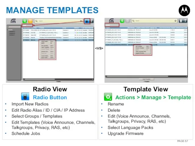
Radio View
Radio Button
Import New Radios
Edit Radio Alias / ID /
MANAGE TEMPLATES
Radio View
Radio Button
Import New Radios
Edit Radio Alias / ID /
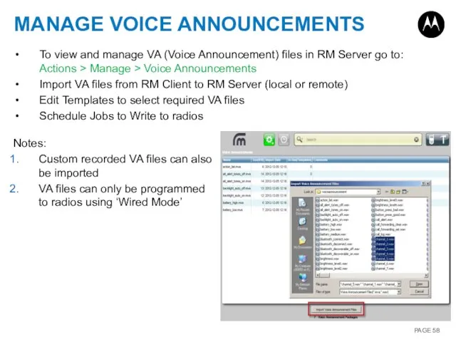
MANAGE VOICE ANNOUNCEMENTS
To view and manage VA (Voice Announcement) files in
MANAGE VOICE ANNOUNCEMENTS
To view and manage VA (Voice Announcement) files in
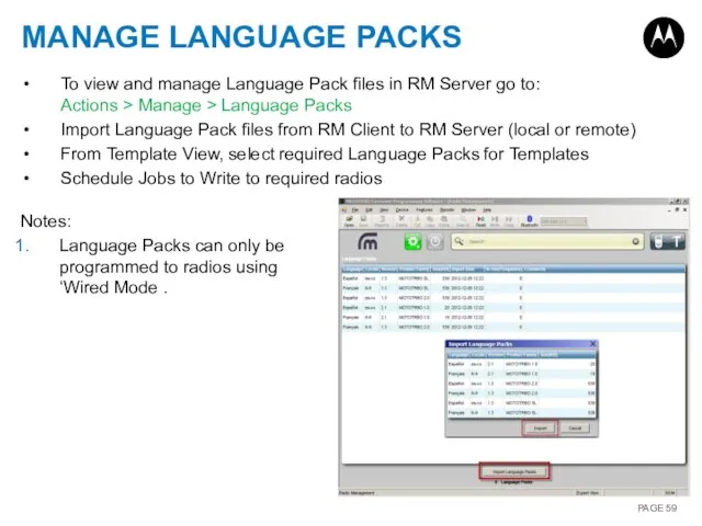
MANAGE LANGUAGE PACKS
To view and manage Language Pack files in RM
MANAGE LANGUAGE PACKS
To view and manage Language Pack files in RM
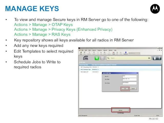
MANAGE KEYS
To view and manage Secure keys in RM Server go
MANAGE KEYS
To view and manage Secure keys in RM Server go
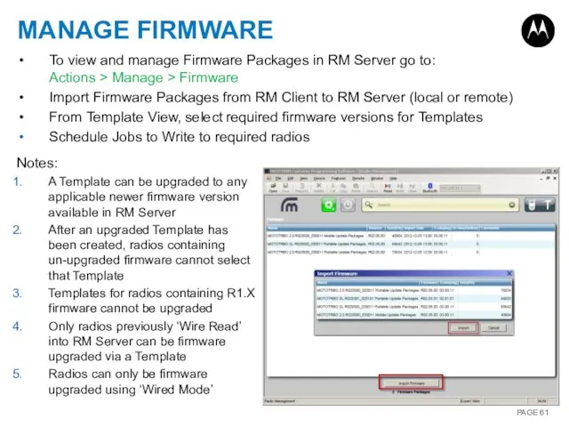
MANAGE FIRMWARE
To view and manage Firmware Packages in RM Server go
MANAGE FIRMWARE
To view and manage Firmware Packages in RM Server go
MULTI-RADIO PROGRAMMING (WIN 7)
Automatic sequential programming of up to 16 radios
MULTI-RADIO PROGRAMMING (WIN 7)
Automatic sequential programming of up to 16 radios
Похожие презентации
 Базовые определения схемотехнического проектирования
 Кто ты из Гравити Фолз?
 Fêtes en France
 Гвозди. Виды гвоздей (5 класс)
 20170509_prezentatsiya_vneklassnogo_meropriyatiya_matematicheskiy_kaleydoskop
 Руководство_пользователя_для_онлайн_курса_ГПА
 Технология производства качокавалло
 20150223_obshchenie._urok_2
 Материаловедение. Алюминиевые сплавы
 20160227_elektronnyy_uchebnik_dlya_nachalnogo_i_srednego_professionalnogo_obrazovaniya
 Моя любимая мама (для школьников)
 Презентация автомобилей женевского автосалона 2008
 Сосны
Сосны Система договоров оптового рынка электроэнергии после 01.04.2006
 Мой выбор профессии
 Игра Brain Штурм
 winter clothes _ memory _ by Artem Morozov
 пасха 2017
 20140704_proektnaya_deyatelnost_kak_sredstvo_realizatsii_fgos_na_urokakh
 Modern equipment and devices in railway transport
 Урок 15. Периметр
 Тепловая схема турбоустановки ТЭЦ МЭИ
 20140911_kashpurov
 Плетёные листья
 20151102_brestskiy-mir_
 Ай да мы!
 Презентация инструкция для участников олимпиады