- Multivariable process control system

Содержание
- 2. Multivariable Process Control System (Flow, Level, Temperature, Pressure) Volume 1/2 Made by: Sharafatdin Yessirkepov Checked by:
- 3. Plan Part 1. Introduction to FLTP Part 2. Main Units of the trainer Part 3. Control
- 4. Introduction How do we control the tank in the field without the manual control? Do we
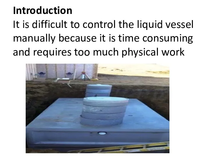
- 5. Introduction It is difficult to control the liquid vessel manually because it is time consuming and
- 6. Introduction (Cont’d) Therefore, the Process Control System is helpful by controlling the unit parameters even at
- 7. Introduction Cont’d Multivariable Process Control System can control the flow rate, level, Pressure and Temperature of
- 8. External Process Unit FLTP-U/EV Basic panel
- 9. 1) Main Units of the trainer FLTP 1)Power supply unit mod. FLTP-A/EV 2) Module for temperature
- 10. 1.1 Power Supply Unit (FLTP-A/EV) Consists of 5 windows 1st window has 4 potentiometers of the
- 11. 1.2 Module for temperature control mod. FLTP-B/EV Has Conditioner on the left side Has Amplifier on
- 12. Question Which kind of thermocouples do you know?
- 13. http://digital.ni.com/public.nsf/allkb/29FC44A9C662D80186256B02008387CF For FLTP Conditioner Thermocouple J STT – Smart Temp. Transmitter NTC – Negative Temperature Coefficient
- 14. 1.2.1 Module for temperature control mod. FLTP-B/EV Has Conditioner on the left side and deals with
- 15. Question. What is amplifier?
- 16. 1.2.2 Amplifier (Brief explanation) Amplifier – modulates the output stronger than input signal For example: Input
- 17. 1.3. Flow Rate- Level Control (FLTP-C/EV) Has 2 conditioners, 1 amplifier and 2 controllers Flow rates
- 18. 1.3.1 Flow Rate Control Measures the flow rate with a paddle wheel Unit : l/min Has
- 19. 1.3.2 Level Control Shows the level of the tank Measured with piezometric sensor
- 20. 1.4 Pressure Unit (FLTP-D/EV) Has signal conditioner and amplifier Pressure is measured in bars. Has 1
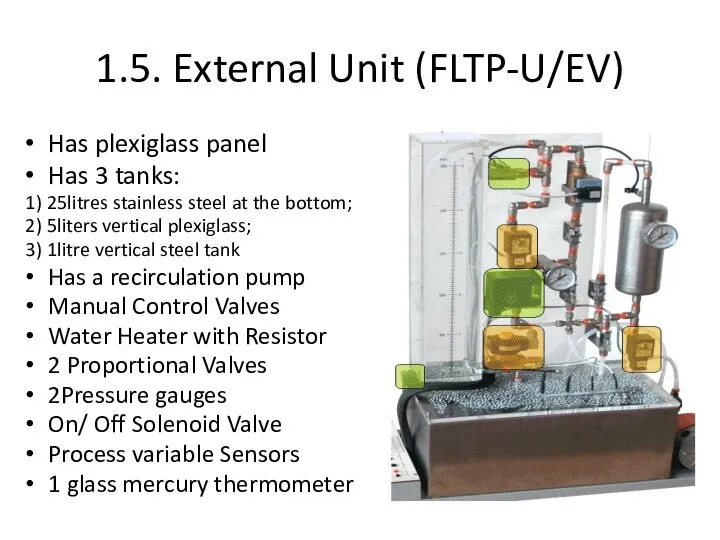
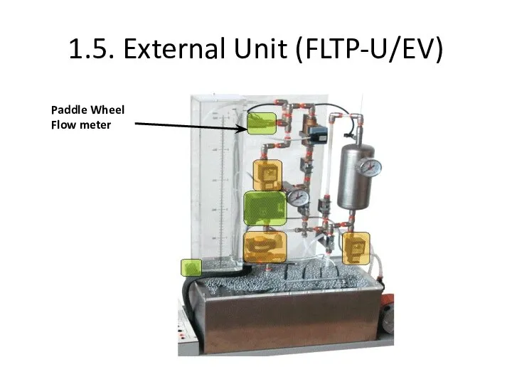
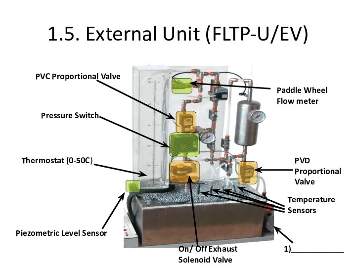
- 21. 1.5. External Unit (FLTP-U/EV) Has plexiglass panel Has 3 tanks: 1) 25litres stainless steel at the
- 22. 1.5. External Unit (FLTP-U/EV) Piezometric Level Sensor
- 23. 1.5. External Unit (FLTP-U/EV) Thermostat (0-50C)
- 24. 1.5. External Unit (FLTP-U/EV) On/ Off Exhaust Solenoid Valve
- 25. 1.5. External Unit (FLTP-U/EV) Pressure Switch
- 26. 1.5. External Unit (FLTP-U/EV) PVC Proportional Valve
- 27. 1.5. External Unit (FLTP-U/EV) Paddle Wheel Flow meter
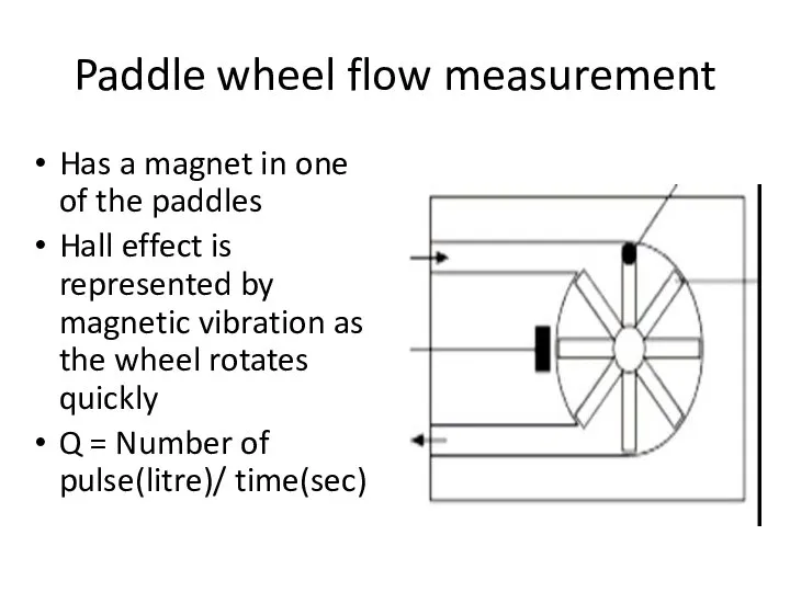
- 28. Paddle wheel flow measurement Has a magnet in one of the paddles Hall effect is represented
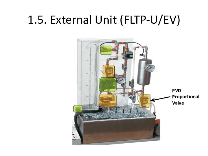
- 29. 1.5. External Unit (FLTP-U/EV) PVD Proportional Valve
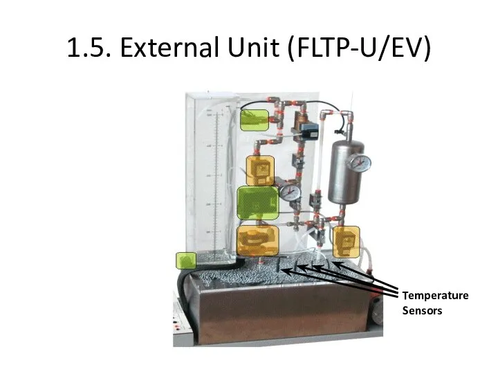
- 30. 1.5. External Unit (FLTP-U/EV) Temperature Sensors
- 31. 1.5. External Unit (FLTP-U/EV) PVC Proportional Valve PVD Proportional Valve Pressure Switch Thermostat (0-50C) Piezometric Level
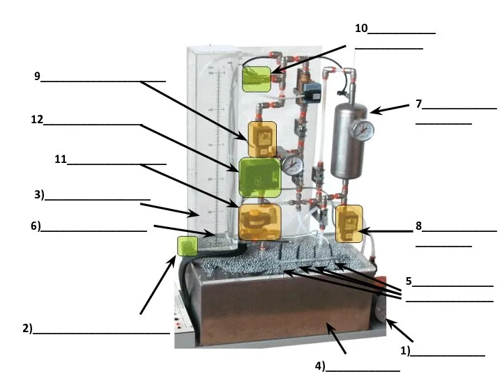
- 32. 9____________________ 8_____________________ 11________________ 6)_________________ 2)______________________ 5___________________________ 10______________________ 1)____________ 3)_________________ 4)____________ 7_____________________ 12________________
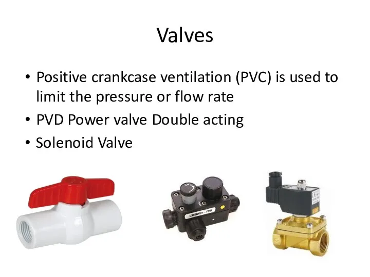
- 33. Valves Positive crankcase ventilation (PVC) is used to limit the pressure or flow rate PVD Power
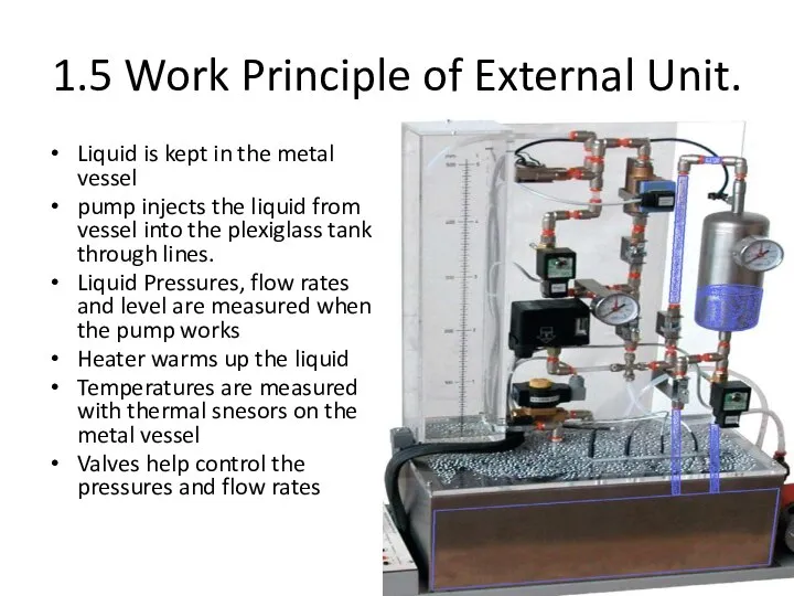
- 34. 1.5 Work Principle of External Unit. Liquid is kept in the metal vessel pump injects the
- 35. 2. Control Units PLC Trainer Industrial PID Control Card
- 36. 2.1 PLC Trainer (PLC-5A/EV) Учебная панель Has 16 digital inputs 14 digital outputs 4 Analog Inputs
- 37. 2.2 PID Controller Has inputs Outputs
- 38. Control Card (MFI-U/EV) Has 8Digital Inputs; 8Digital Outputs 16 Analog inputs 2 Analog Outputs
- 39. 3 Control Techniques PID Control Amplifier Heater Transducer Signal Conditioner Set-Point
- 40. Question. Is it open loop or closed loop control? PID Control Amplifier Heater Transducer Signal Conditioner
- 41. Answer: It is closed loop control because of PID Control and feedback PID Control Amplifier Heater
- 42. Open Loop Control Signal Conditioner
- 43. Question What are the transducers?
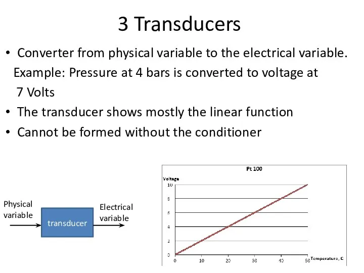
- 44. 3 Transducers Converter from physical variable to the electrical variable. Example: Pressure at 4 bars is
- 45. Question What is the Conditioner?
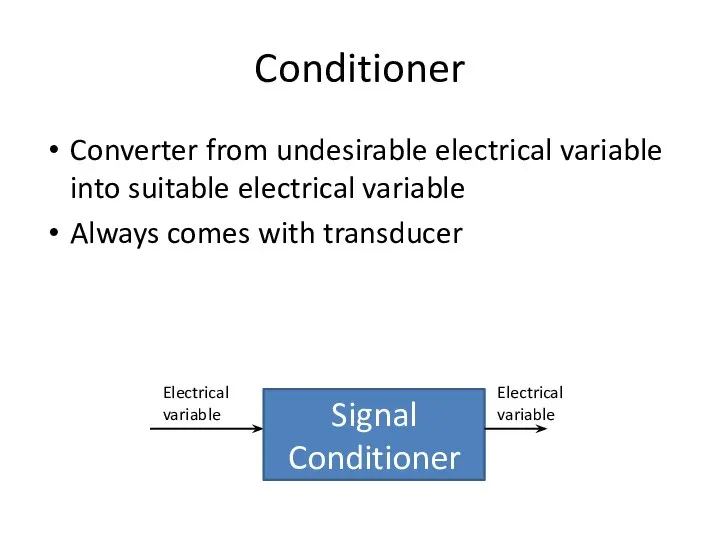
- 46. Conditioner Converter from undesirable electrical variable into suitable electrical variable Always comes with transducer Signal Conditioner
- 47. Temperature Control PID Control Amplifier Heater Transducer Signal Conditioner Set-Point PV
- 48. Pressure Control PID Control Amplifier Pump Transducer Signal Conditioner Set-Point PV
- 50. Скачать презентацию
Multivariable Process Control System (Flow, Level, Temperature, Pressure) Volume 1/2
Multivariable Process Control System (Flow, Level, Temperature, Pressure) Volume 1/2
Plan
Part 1. Introduction to FLTP
Part 2. Main Units of the trainer
Part
Plan Part 1. Introduction to FLTP Part 2. Main Units of the trainer Part
Introduction
How do we control the tank in the field without the
Introduction How do we control the tank in the field without the
Introduction
It is difficult to control the liquid vessel manually because it
Introduction It is difficult to control the liquid vessel manually because it
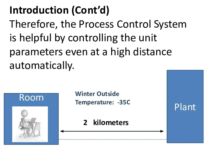
Introduction (Cont’d)
Therefore, the Process Control System is helpful by controlling the
Introduction (Cont’d) Therefore, the Process Control System is helpful by controlling the
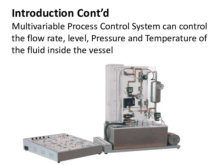
Introduction Cont’d
Multivariable Process Control System can control the flow rate, level,
Introduction Cont’d Multivariable Process Control System can control the flow rate, level,
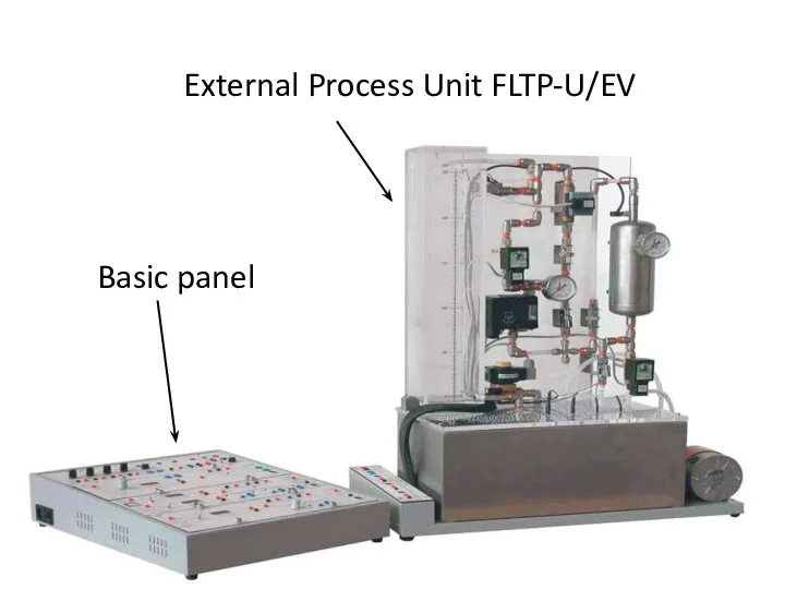
External Process Unit FLTP-U/EV
Basic panel
External Process Unit FLTP-U/EV
Basic panel
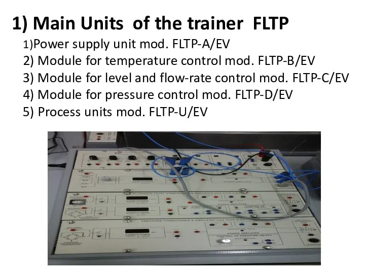
1) Main Units of the trainer FLTP
1)Power supply unit
1) Main Units of the trainer FLTP 1)Power supply unit
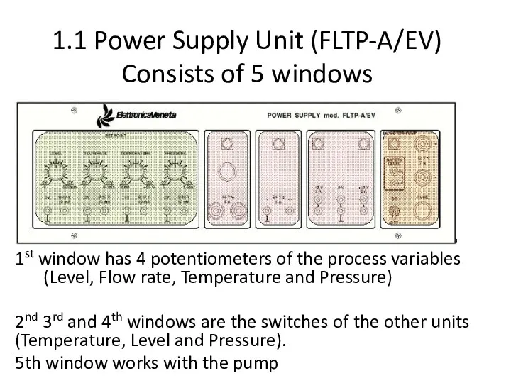
1.1 Power Supply Unit (FLTP-A/EV)
Consists of 5 windows
1st window has 4
1.1 Power Supply Unit (FLTP-A/EV)
Consists of 5 windows
1st window has 4
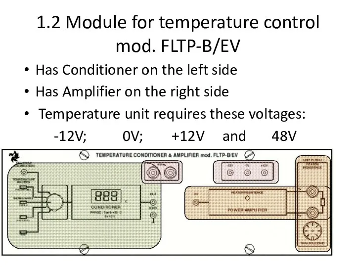
1.2 Module for temperature control mod. FLTP-B/EV
Has Conditioner on the left
1.2 Module for temperature control mod. FLTP-B/EV
Has Conditioner on the left
Question
Which kind of thermocouples do you know?
Question
Which kind of thermocouples do you know?
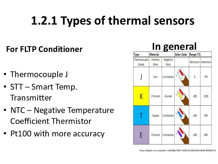
http://digital.ni.com/public.nsf/allkb/29FC44A9C662D80186256B02008387CF
For FLTP Conditioner
Thermocouple J
STT – Smart Temp. Transmitter
NTC – Negative
http://digital.ni.com/public.nsf/allkb/29FC44A9C662D80186256B02008387CF
For FLTP Conditioner
Thermocouple J
STT – Smart Temp. Transmitter
NTC – Negative
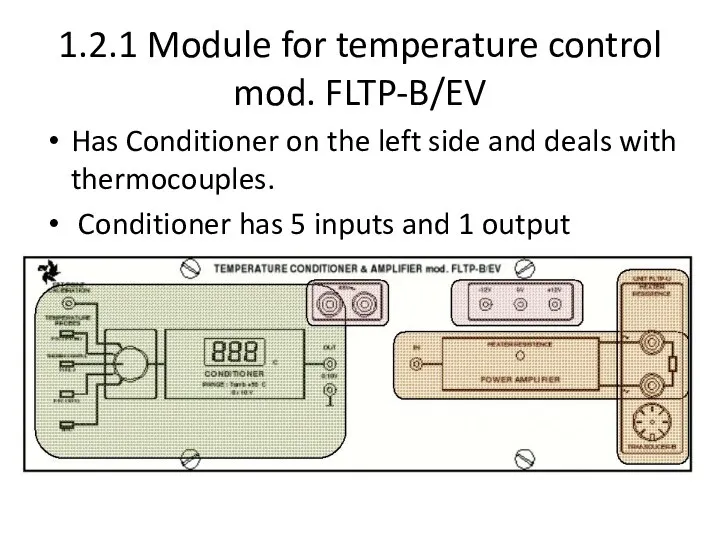
1.2.1 Module for temperature control mod. FLTP-B/EV
Has Conditioner on the left
1.2.1 Module for temperature control mod. FLTP-B/EV
Has Conditioner on the left
Question.
What is amplifier?
Question.
What is amplifier?
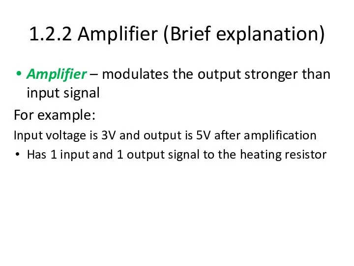
1.2.2 Amplifier (Brief explanation)
Amplifier – modulates the output stronger than
1.2.2 Amplifier (Brief explanation)
Amplifier – modulates the output stronger than
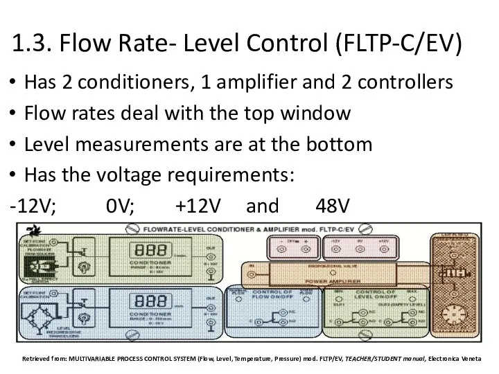
1.3. Flow Rate- Level Control (FLTP-C/EV)
Has 2 conditioners, 1 amplifier and
1.3. Flow Rate- Level Control (FLTP-C/EV)
Has 2 conditioners, 1 amplifier and
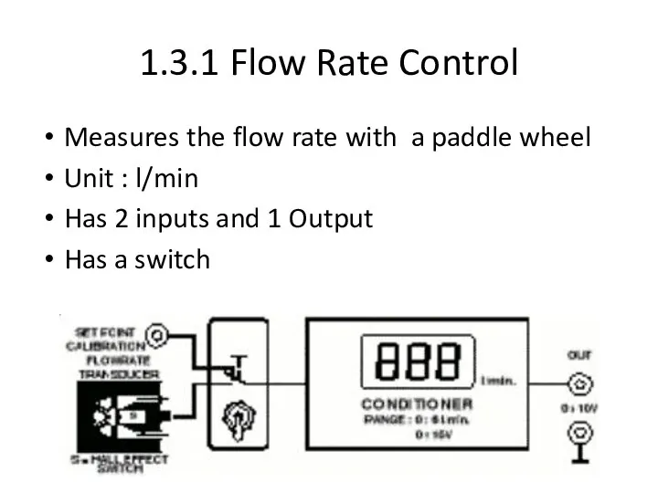
1.3.1 Flow Rate Control
Measures the flow rate with a paddle wheel
Unit
1.3.1 Flow Rate Control
Measures the flow rate with a paddle wheel
Unit
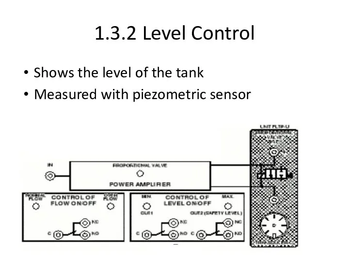
1.3.2 Level Control
Shows the level of the tank
Measured with piezometric sensor
1.3.2 Level Control
Shows the level of the tank
Measured with piezometric sensor
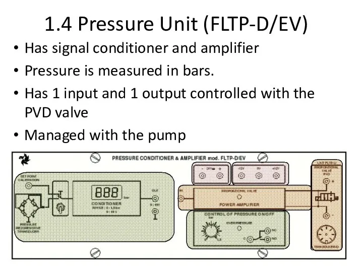
1.4 Pressure Unit (FLTP-D/EV)
Has signal conditioner and amplifier
Pressure is measured in
1.4 Pressure Unit (FLTP-D/EV)
Has signal conditioner and amplifier
Pressure is measured in
1.5. External Unit (FLTP-U/EV)
Has plexiglass panel
Has 3 tanks:
1) 25litres stainless
1.5. External Unit (FLTP-U/EV)
Has plexiglass panel
Has 3 tanks:
1) 25litres stainless
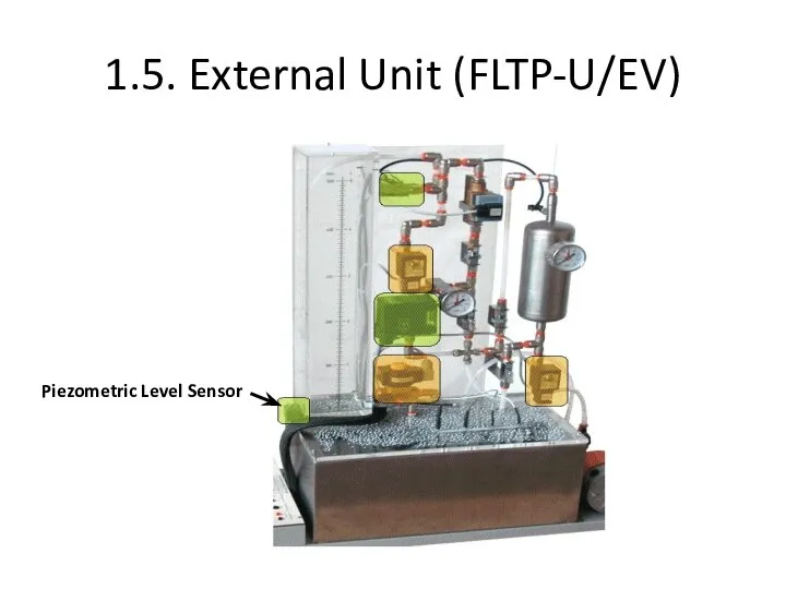
1.5. External Unit (FLTP-U/EV)
Piezometric Level Sensor
1.5. External Unit (FLTP-U/EV)
Piezometric Level Sensor

1.5. External Unit (FLTP-U/EV)
Thermostat (0-50C)
1.5. External Unit (FLTP-U/EV)
Thermostat (0-50C)
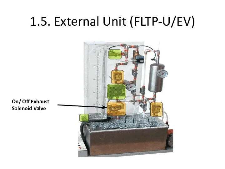
1.5. External Unit (FLTP-U/EV)
On/ Off Exhaust Solenoid Valve
1.5. External Unit (FLTP-U/EV)
On/ Off Exhaust Solenoid Valve
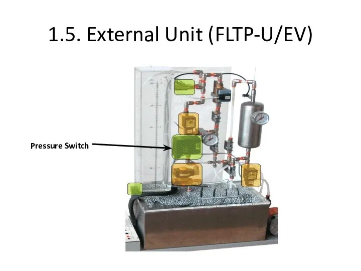
1.5. External Unit (FLTP-U/EV)
Pressure Switch
1.5. External Unit (FLTP-U/EV)
Pressure Switch
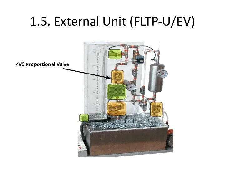
1.5. External Unit (FLTP-U/EV)
PVC Proportional Valve
1.5. External Unit (FLTP-U/EV)
PVC Proportional Valve
1.5. External Unit (FLTP-U/EV)
Paddle Wheel Flow meter
1.5. External Unit (FLTP-U/EV)
Paddle Wheel Flow meter
Paddle wheel flow measurement
Has a magnet in one of the paddles
Hall
Paddle wheel flow measurement
Has a magnet in one of the paddles
Hall
1.5. External Unit (FLTP-U/EV)
PVD Proportional Valve
1.5. External Unit (FLTP-U/EV)
PVD Proportional Valve
1.5. External Unit (FLTP-U/EV)
Temperature Sensors
1.5. External Unit (FLTP-U/EV)
Temperature Sensors
1.5. External Unit (FLTP-U/EV)
PVC Proportional Valve
PVD Proportional Valve
Pressure Switch
Thermostat (0-50C)
Piezometric Level
1.5. External Unit (FLTP-U/EV)
PVC Proportional Valve
PVD Proportional Valve
Pressure Switch
Thermostat (0-50C)
Piezometric Level
9____________________
8_____________________
11________________
6)_________________
2)______________________
5___________________________
10______________________
1)____________
3)_________________
4)____________
7_____________________
12________________
9____________________
8_____________________
11________________
6)_________________
2)______________________
5___________________________
10______________________
1)____________
3)_________________
4)____________
7_____________________
12________________
Valves
Positive crankcase ventilation (PVC) is used to limit the pressure or
Valves
Positive crankcase ventilation (PVC) is used to limit the pressure or
1.5 Work Principle of External Unit.
Liquid is kept in the
1.5 Work Principle of External Unit.
Liquid is kept in the
2. Control Units
PLC Trainer
Industrial PID
Control Card
2. Control Units
PLC Trainer
Industrial PID
Control Card
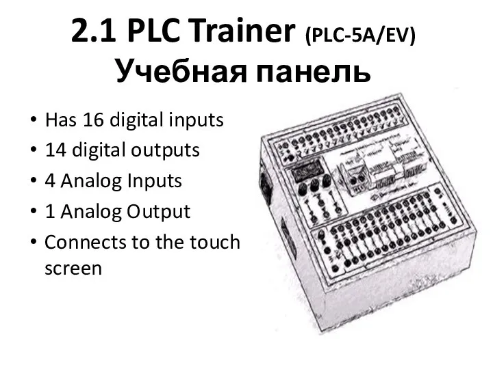
2.1 PLC Trainer (PLC-5A/EV)
Учебная панель
Has 16 digital inputs
14 digital outputs
4 Analog
2.1 PLC Trainer (PLC-5A/EV)
Учебная панель
Has 16 digital inputs
14 digital outputs
4 Analog
2.2 PID Controller
Has inputs
Outputs
2.2 PID Controller
Has inputs
Outputs
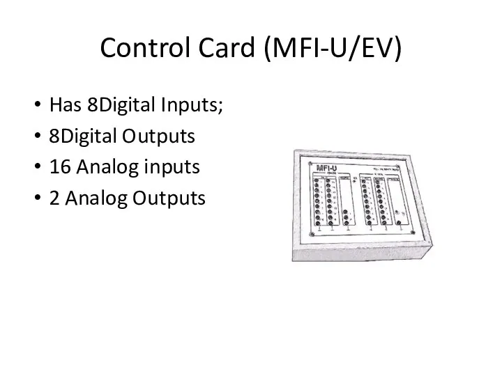
Control Card (MFI-U/EV)
Has 8Digital Inputs;
8Digital Outputs
16 Analog inputs
2 Analog Outputs
Control Card (MFI-U/EV)
Has 8Digital Inputs;
8Digital Outputs
16 Analog inputs
2 Analog Outputs
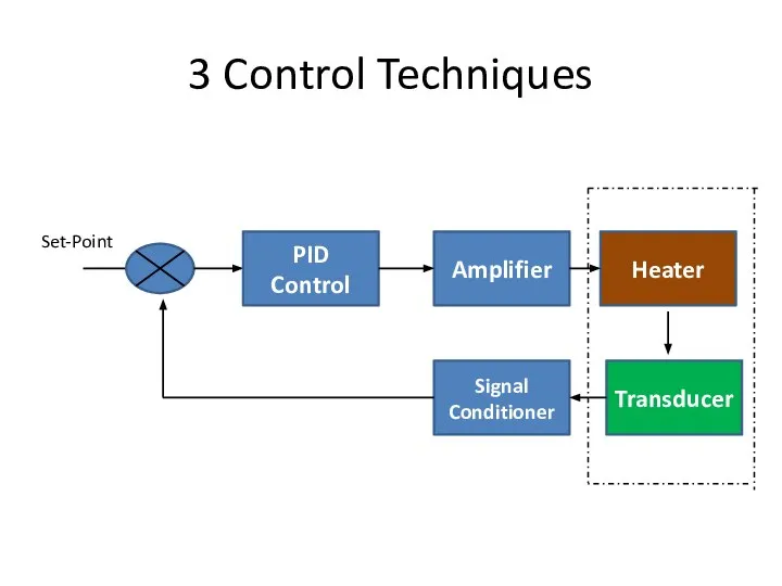
3 Control Techniques
PID Control
Amplifier
Heater
Transducer
Signal Conditioner
Set-Point
3 Control Techniques
PID Control
Amplifier
Heater
Transducer
Signal Conditioner
Set-Point
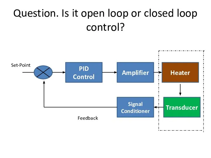
Question. Is it open loop or closed loop control?
PID Control
Amplifier
Heater
Transducer
Signal Conditioner
Set-Point
Feedback
Question. Is it open loop or closed loop control?
PID Control
Amplifier
Heater
Transducer
Signal Conditioner
Set-Point
Feedback
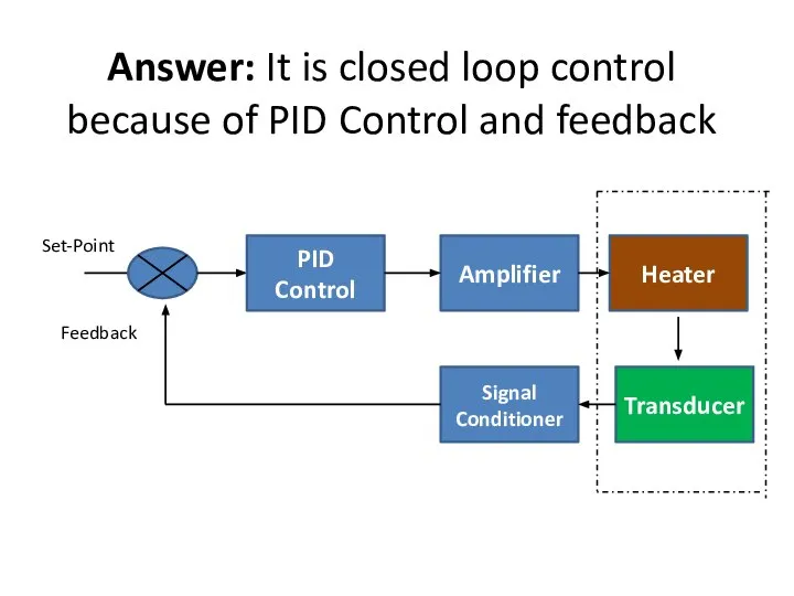
Answer: It is closed loop control
because of PID Control and feedback
PID
Answer: It is closed loop control
because of PID Control and feedback
PID
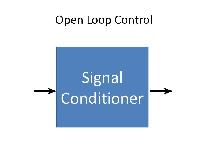
Open Loop Control
Signal Conditioner
Open Loop Control
Signal Conditioner
Question
What are the transducers?
Question
What are the transducers?
3 Transducers
Converter from physical variable to the electrical variable.
Example: Pressure
3 Transducers
Converter from physical variable to the electrical variable.
Example: Pressure
Question
What is the Conditioner?
Question
What is the Conditioner?
Conditioner
Converter from undesirable electrical variable into suitable electrical variable
Always comes with
Conditioner
Converter from undesirable electrical variable into suitable electrical variable
Always comes with
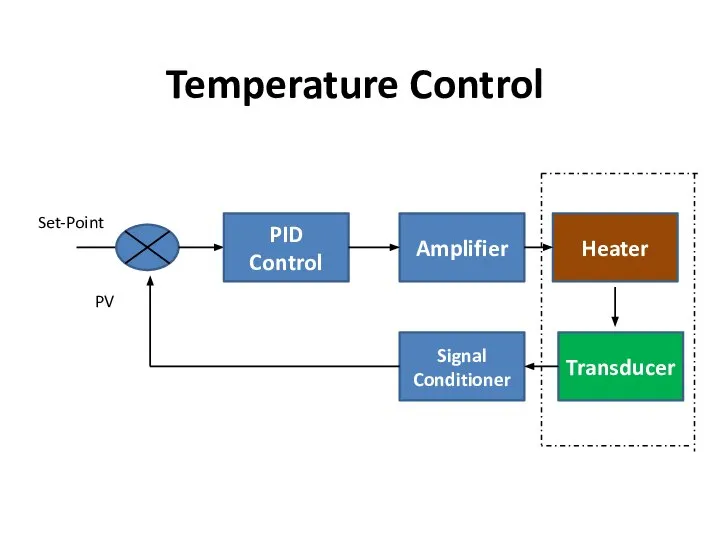
Temperature Control
PID Control
Amplifier
Heater
Transducer
Signal Conditioner
Set-Point
PV
Temperature Control
PID Control
Amplifier
Heater
Transducer
Signal Conditioner
Set-Point
PV
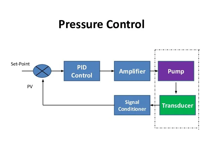
Pressure Control
PID Control
Amplifier
Pump
Transducer
Signal Conditioner
Set-Point
PV
Pressure Control
PID Control
Amplifier
Pump
Transducer
Signal Conditioner
Set-Point
PV
 день мира
 Sara Sewastianik- instalacja wodociągowa- poprawiona
 Система управления регионами. (Тема 4)
 Пиелонефрит укр
 Орындаған: Құмарбекова Н.Е Қабылдаған: Қожекенова Ж.А. Топ: 10-011-02қ Факультет: жалпы медицина
 Уголовно-правовые аспекты противодействия незаконному перемещению через границу объектов дикой флоры и фауны Курамшина Ольга
  Формулировка диагноза при черепно-мозговой травме Состоит из двух частей
  Презентация "Французский классицизм XVII века" - скачать презентации по МХК
 My idol - Pavel Datsyuk
 Соединения с натягом
 Фразеологизмы из Библии
 УЧЕНИЧЕСКОЕ САМОУПРАВЛЕНИЕ МОУ НИЖНЕПОДКУМСКОЙ СОШ №24 ГОРОДА ПЯТИГОРСКА Совет старост
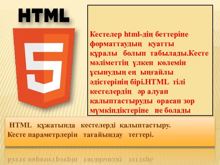 HTML құжатында кестелерді қалыптастыру. Кесте параметрлерін тағайындау тегтері
 Технические средства радиосвязи. Для различных должностных категорий обучающихся
 Быт XIV-XV веков
 Оценка эффективности ажиотажного маркетинга в социальных медиа Агентство веб-коммуникаций ErstMedia. - презентация
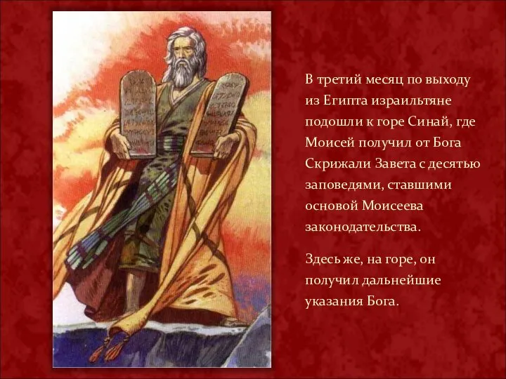 В третий месяц по выходу из Египта израильтяне подошли к горе Синай, где Моисей получил от Бога Скрижали Завета с десятью заповедям
 Определители и способы их вычисления
  Сущность менеджмента продаж, понятие и функции. Ершова Ирина, Грабер Оля
 Remotely Controlling Devices
 Использование ИКТ на уроках истории и обществознания при подготовке к ЕГЭ Подготовила: учитель истории и обществознания МОУСОШ 34
 Презентация Краткий конспект лекции по микроэкономике с использованием статистических баз официальных сайтов
  Архитектура барокко
  Методы решения систем уравнений МОУ - СОШ №6 Учитель математики Миссюра Ирина Николаевна
 Горнолыжные курорты Южной Кореи
 . Многогранный угол
 Парки и социальные проблемы начала XXI века
 Інтернет: розуміти більше, досягати більшого