- Video wall controller spec

Содержание
- 2. Function : • Full hardware architecture,Without CPU and Operation system; • Start-upTime less than 6ms; •
- 3. • Thermostatically controlled fan Embedded Thermostatically controlled fan,can adjust the fan's operation according to the actural
- 4. System Connection(2X2):
- 5. Part 2 : Intergrated Controller Interface
- 6. Part 3:Control Software Instruction Software Operating Environment Operation system: Windows 98/2000/ NT/XP/WIN7/ WIN8/WIN8.1/WIN10/Vista, Minimum CPU:Pentium 133Mhz
- 7. 3,Software Interface
- 8. HDMI cable connection for matrix device all the monitor's HDMI port should connected with the HDMI
- 9. COM port Settings Click " Setting " - "Comm " 1)Choose the correct COM port ,System
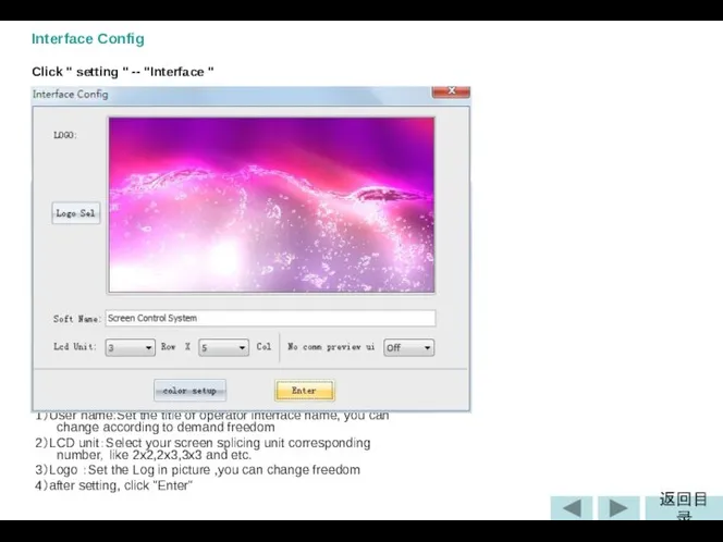
- 10. Interface Config Click " setting " -- "Interface " 1)User name:Set the title of operator interface
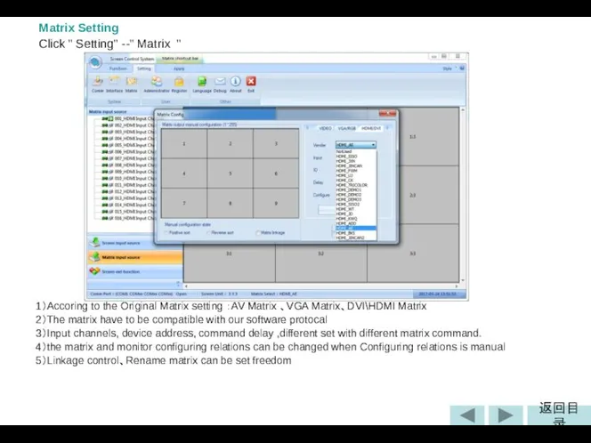
- 11. Matrix Setting Click " Setting" --" Matrix " 1)Accoring to the Original Matrix setting :AV Matrix
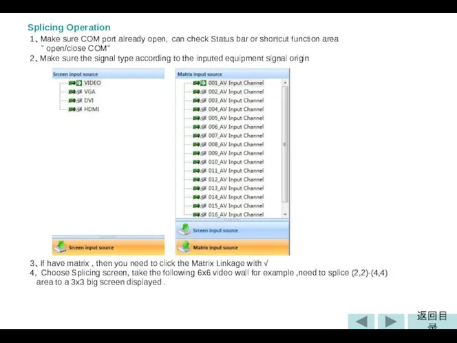
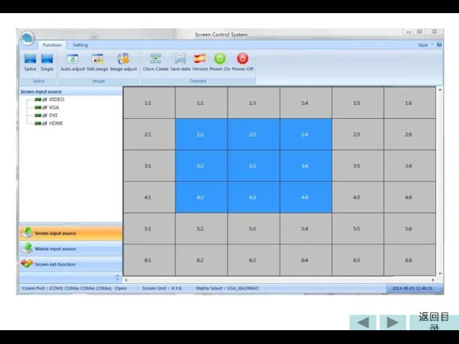
- 12. Splicing Operation 1、Make sure COM port already open,can check Status bar or shortcut function area "
- 14. 5、Select the correct signal input type and Matrix input channel , like: VIDEO,001_AV matrix input channel
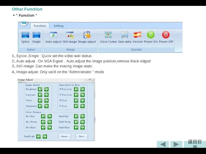
- 15. Other Function • “ Function ” 1、Splice ,Single :Quick set the video wall status 2、Auto-adjust :On
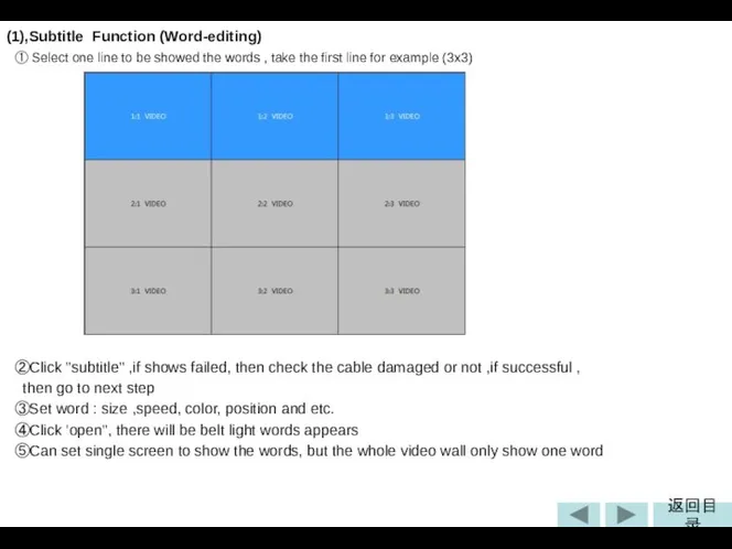
- 16. (1),Subtitle Function (Word-editing) ① Select one line to be showed the words , take the first
- 17. ⑥、Close-Comm:On the case of the correct set of Com port ,can click this to open/close Com
- 18. (2)Frame function (3)Soft DIP Setting (Dial) First ,the software interface H/V is the same with the
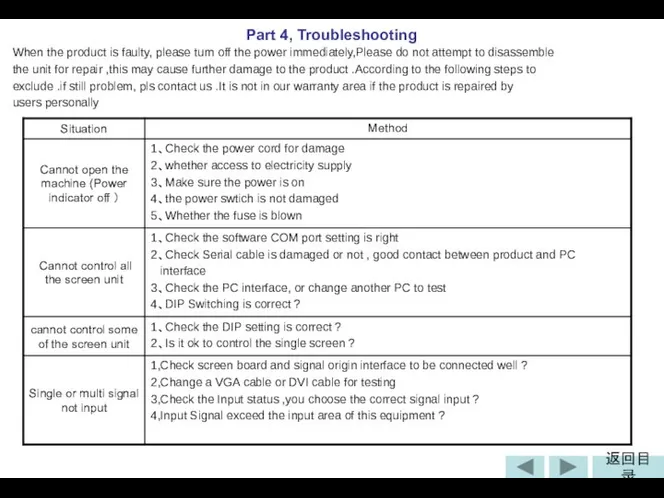
- 19. When the product is faulty, please turn off the power immediately,Please do not attempt to disassemble
- 21. Скачать презентацию
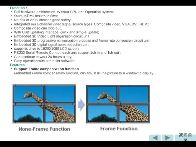
Function :
• Full hardware architecture,Without CPU and Operation system;
Function :
• Full hardware architecture,Without CPU and Operation system;
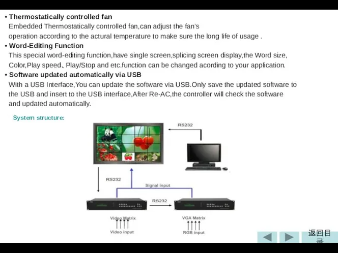
• Thermostatically controlled fan
Embedded Thermostatically controlled fan,can adjust the fan's
• Thermostatically controlled fan
Embedded Thermostatically controlled fan,can adjust the fan's
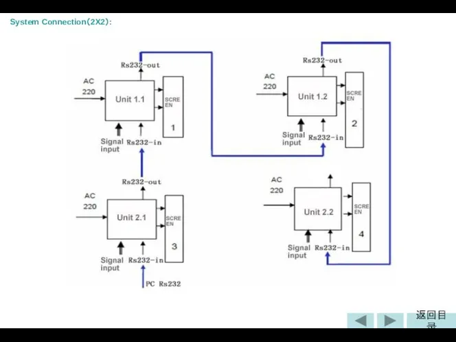
System Connection(2X2):
System Connection(2X2):
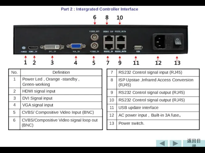
Part 2 : Intergrated Controller Interface
Part 2 : Intergrated Controller Interface
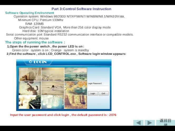
Part 3:Control Software Instruction
Software Operating Environment
Operation system: Windows
Part 3:Control Software Instruction
Software Operating Environment
Operation system: Windows
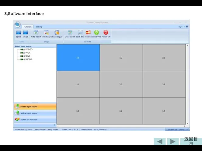
3,Software Interface
3,Software Interface
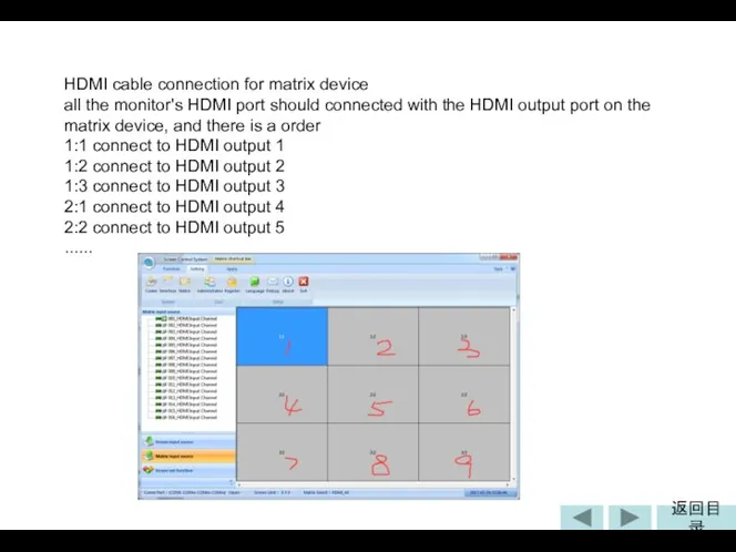
HDMI cable connection for matrix device
all the monitor's HDMI port should
HDMI cable connection for matrix device
all the monitor's HDMI port should
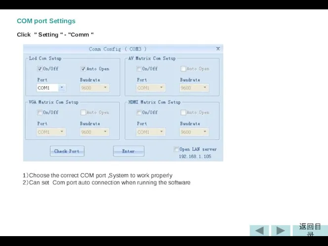
COM port Settings
Click " Setting " - "Comm "
1)Choose the
COM port Settings
Click " Setting " - "Comm "
1)Choose the
Interface Config
Click " setting " -- "Interface "
1)User name:Set the title
Interface Config
Click " setting " -- "Interface "
1)User name:Set the title
Matrix Setting
Click " Setting" --" Matrix "
1)Accoring to
Matrix Setting
Click " Setting" --" Matrix "
1)Accoring to
Splicing Operation
1、Make sure COM port already open,can check Status
Splicing Operation
1、Make sure COM port already open,can check Status
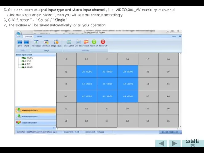
5、Select the correct signal input type and Matrix input channel
5、Select the correct signal input type and Matrix input channel
Other Function
• “ Function ”
1、Splice ,Single :Quick set the
Other Function
• “ Function ”
1、Splice ,Single :Quick set the
(1),Subtitle Function (Word-editing)
① Select one line to be showed the
(1),Subtitle Function (Word-editing)
① Select one line to be showed the
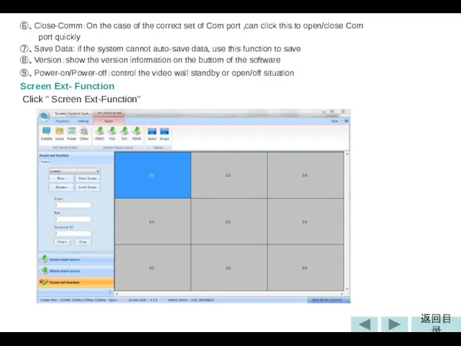
⑥、Close-Comm:On the case of the correct set of Com port ,can
⑥、Close-Comm:On the case of the correct set of Com port ,can
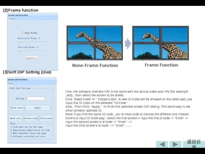
(2)Frame function
(3)Soft DIP Setting (Dial)
First ,the software interface H/V is the
(2)Frame function
(3)Soft DIP Setting (Dial)
First ,the software interface H/V is the
 Зимние виды спорта
 Области действия идентификаторов.
 Политическая партия как объект социологического анализа
 Торможение в ВНД
 Графический метод решения системы линейных уравнений с двумя переменными
  ИРРАЦИОНАЛЬНЫЕ УРАВНЕНИЯ
 Поворотная и неповоротная тележки. Вагон трамвайный модели 71-931 Витязь
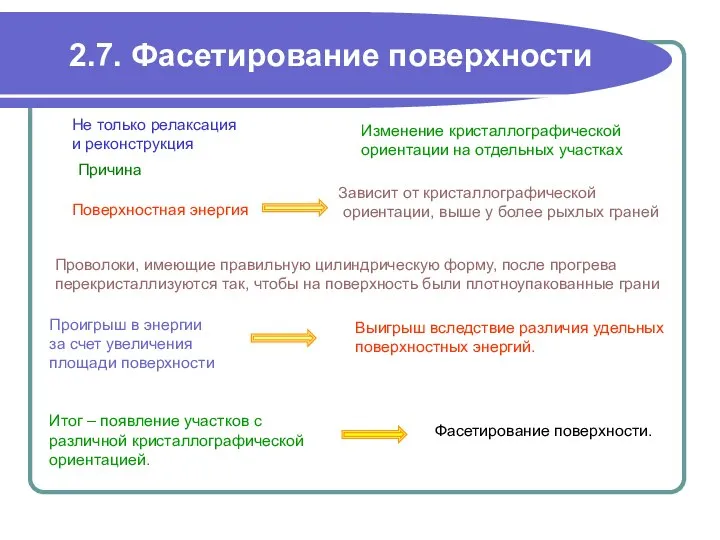 Фасетирование поверхности
 Garden of Russian museum
 Типизация и унификация в строительстве. Модульная система и параметры зданий
 Неопределенный интеграл Лекция7
 Толстопленочная технология. Область применения
 Изучение и практическое внедрение инструментов ПСР на пилотном участке ФГУП ФНПЦ «ПО «Старт» им. М.В. Проценко»
 Учитель начальных классов Болховитина Л.И. Учитель начальных классов Болховитина Л.И. СОУ «Средняя общеобразовательная школа №3
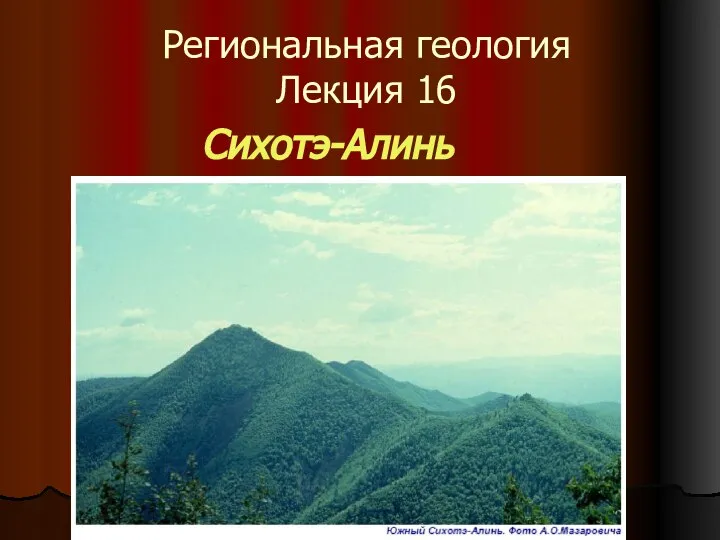 Региональная геология
  Планирование и экономический анализ деятельности лечебных подразделений Заместитель исполнительного директора ТФ ОМС по эко
 Награды СССР. Высшие степени отличия СССР
 Презентация Таможенный контроль за соблюдением порядка перемещения товаров трубопроводным способом
 ScrumTrek Эффективные процессы
 Индо-буддийский тип культуры: проблема религиозного взаимодействия
 Пантеизм и новая космология
 Автоматические балансировочные клапаны
 Оформление дипломных проектов
 Синьора сосиска - презентация для начальной школы
 Презентация на тему "Туберкулез -Чума ХХІ века" - скачать презентации по Медицине
 Грамматика языка
 Презентация на тему "Фармакологическая стратегия клеточных технологий" - скачать презентации по Медицине
 Русь расправляет крылья Урок окружающего мира 4 класс Учитель И.Н.Кондратьева