- 080626-GT10 Inverter Quick start guide

Содержание
- 2. Notes In the following Quick Start guide, we will configure a system using the GT10xx-LBD (RS422,
- 3. STEP 1 - HMI Select the Terminal (must have 422 interface), product names and SAP no.:
- 4. STEP 2 – communication cable [6]: User prepared cable (RJ45 patch cable) “568A” “568B” Please check
- 5. STEP 2 – “568B”-type cable [6]: User prepared cable (RJ45 patch cable)
- 6. STEP 3 – Programming cable GT10-RS2TUSB-5S GT09-C30USB-5P Programming Cable HMI Option #1 for Serial connections (9pin,
- 7. Successful Configuration Example GT1030-LBD with RS422 CONNECTION 24VDC Power Supply (+10%,-15%) GT01-C30R2-6P or GT10-RS2TUSB-5S + GT09-C30USB-5P
- 8. STEP 4 – Software 1 GT-Works2 software Suite GT-Designer2 MUST have Version 2. 73B or later
- 9. STEP 4 – Software 2 Select FREQROL driver Install new OS and FREQROL driver to GT10
- 10. STEP 4 – Software 3 Switch GT10 into “OS installation mode” Install new OS and FREQROL
- 11. Inverter Communication settings Note1: Please set P77 = 2, Write during operation enabled. Note2: After changing
- 12. Inverter Commands *1 When creating the screen, designate only either of programmed operation (PG) device or
- 13. Inverter Status Monitor
- 14. Run Command
- 15. Alarm definition
- 16. Special Parameters *1 GOT cannot monitor SP109 to SP111 if the conditions below are satisfied at
- 17. Special Parameter SP122 Example: Forward rotation in RH (high speed) mode: b1 = 1 (value 2)
- 18. Example Screens GT Designer – GT10 to one FR-E700 SP122 for Touch key actions: Fwd =
- 19. GT10 to two FR-E700 in Multi-drop [1]: FR-RJ45-HUBxx + Terminating resistor FR-RJ45-TR [2]: Ethernet Patch cables
- 21. Скачать презентацию
Notes
In the following Quick Start guide, we will configure a system
Notes
In the following Quick Start guide, we will configure a system

STEP 1 - HMI
Select the Terminal
(must have 422 interface), product
STEP 1 - HMI
Select the Terminal (must have 422 interface), product
![STEP 2 – communication cable [6]: User prepared cable (RJ45 patch](/_ipx/f_webp&q_80&fit_contain&s_1440x1080/imagesDir/jpg/569971/slide-3.jpg)
STEP 2 – communication cable
[6]: User prepared cable (RJ45 patch cable)
“568A”
“568B”
Please
check
your
cable:
OR
STEP 2 – communication cable
[6]: User prepared cable (RJ45 patch cable)
“568A”
“568B”
Please
check
your
cable:
OR
![STEP 2 – “568B”-type cable [6]: User prepared cable (RJ45 patch cable)](/_ipx/f_webp&q_80&fit_contain&s_1440x1080/imagesDir/jpg/569971/slide-4.jpg)
STEP 2 – “568B”-type cable
[6]: User prepared cable (RJ45 patch cable)
STEP 2 – “568B”-type cable
[6]: User prepared cable (RJ45 patch cable)
STEP 3 – Programming cable
GT10-RS2TUSB-5S
GT09-C30USB-5P
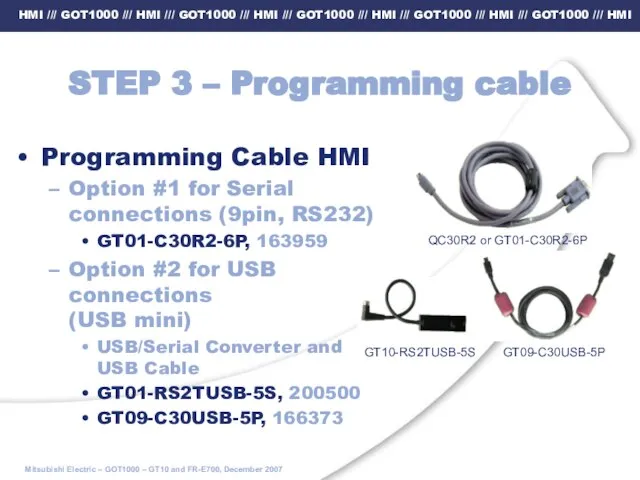
Programming Cable HMI
Option #1 for Serial connections
STEP 3 – Programming cable
GT10-RS2TUSB-5S
GT09-C30USB-5P
Programming Cable HMI
Option #1 for Serial connections
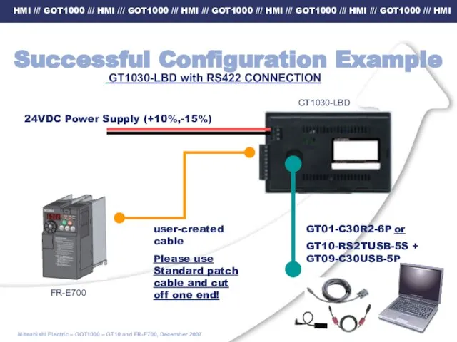
Successful Configuration Example
GT1030-LBD with RS422 CONNECTION
24VDC Power Supply (+10%,-15%)
GT01-C30R2-6P or
GT10-RS2TUSB-5S
Successful Configuration Example
GT1030-LBD with RS422 CONNECTION
24VDC Power Supply (+10%,-15%)
GT01-C30R2-6P or
GT10-RS2TUSB-5S
STEP 4 – Software 1
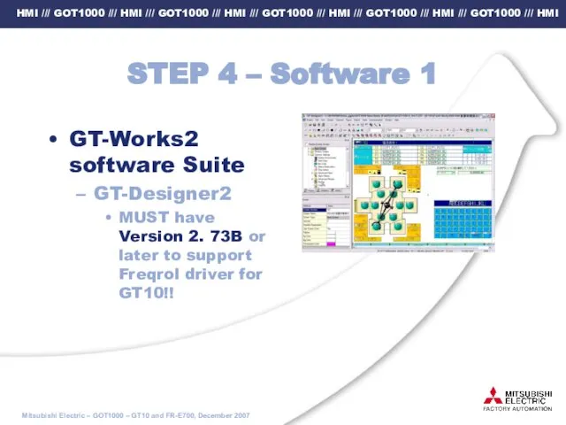
GT-Works2 software Suite
GT-Designer2
MUST have Version 2.
STEP 4 – Software 1
GT-Works2 software Suite
GT-Designer2
MUST have Version 2.
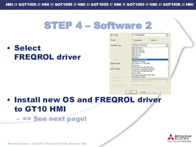
STEP 4 – Software 2
Select
FREQROL driver
Install new OS and FREQROL
STEP 4 – Software 2
Select
FREQROL driver
Install new OS and FREQROL
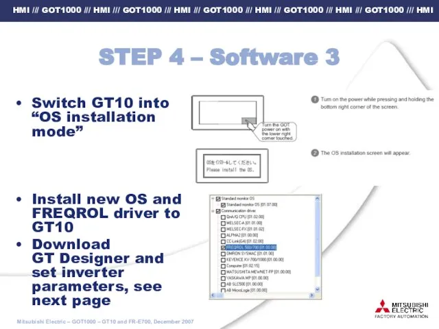
STEP 4 – Software 3
Switch GT10 into “OS installation mode”
Install new
STEP 4 – Software 3
Switch GT10 into “OS installation mode”
Install new
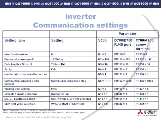
Inverter
Communication settings
Note1: Please set P77 = 2, Write during operation enabled.
Note2:
Inverter
Communication settings
Note1: Please set P77 = 2, Write during operation enabled.
Note2:
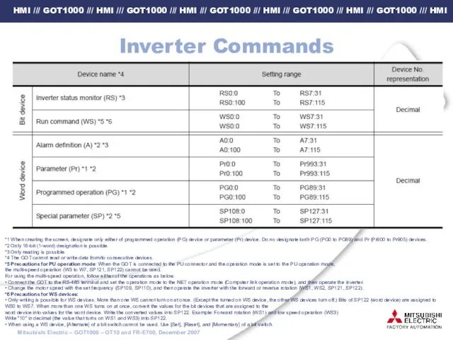
Inverter Commands
*1 When creating the screen, designate only either of programmed
Inverter Commands
*1 When creating the screen, designate only either of programmed
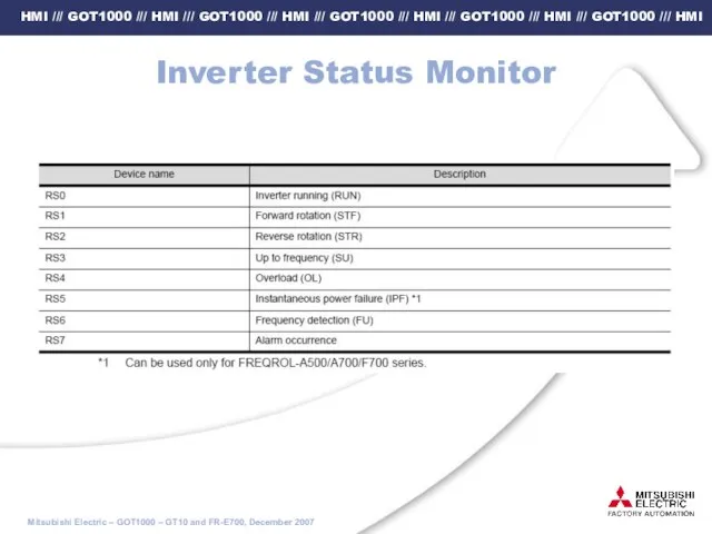
Inverter Status Monitor
Inverter Status Monitor
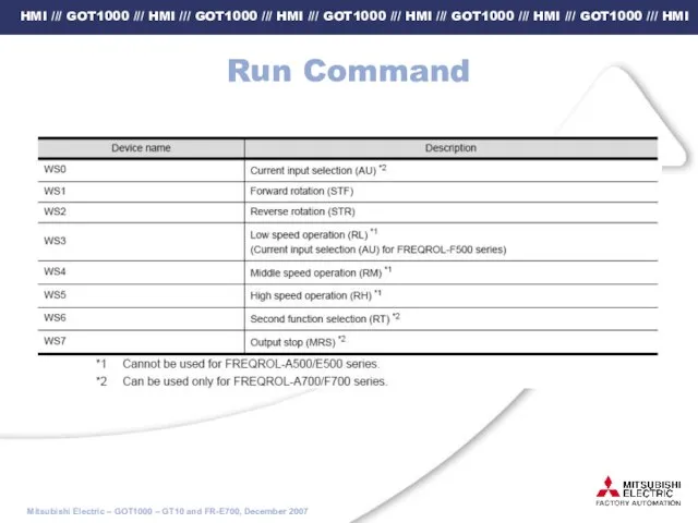
Run Command
Run Command
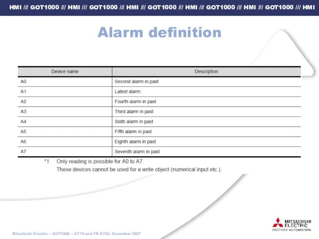
Alarm definition
Alarm definition
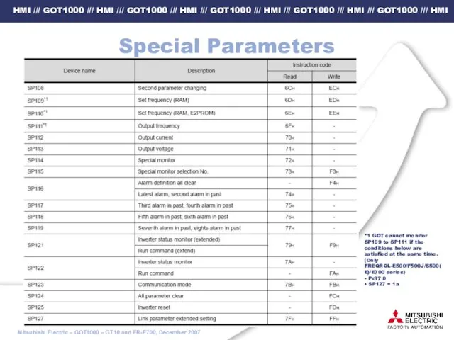
Special Parameters
*1 GOT cannot monitor SP109 to SP111 if the conditions
Special Parameters
*1 GOT cannot monitor SP109 to SP111 if the conditions
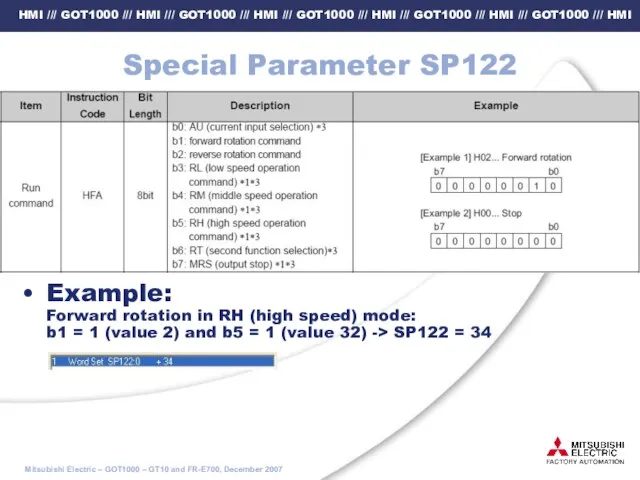
Special Parameter SP122
Example:
Forward rotation in RH (high speed) mode:
b1 = 1
Special Parameter SP122
Example: Forward rotation in RH (high speed) mode: b1 = 1
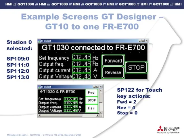
Example Screens GT Designer –
GT10 to one FR-E700
SP122 for Touch key
Example Screens GT Designer –
GT10 to one FR-E700
SP122 for Touch key
![GT10 to two FR-E700 in Multi-drop [1]: FR-RJ45-HUBxx + Terminating resistor](/_ipx/f_webp&q_80&fit_contain&s_1440x1080/imagesDir/jpg/569971/slide-18.jpg)
GT10 to two FR-E700 in Multi-drop
[1]: FR-RJ45-HUBxx + Terminating resistor FR-RJ45-TR
[2]:
GT10 to two FR-E700 in Multi-drop
[1]: FR-RJ45-HUBxx + Terminating resistor FR-RJ45-TR
[2]:
 Количественные показатели надежности
 20141008_pole_chudes_-_vneklassnoe_meropriyatie_dlya_6-8_klassov_na_temu_rossiya_s_drevneyshikh_vremen_do_xix_veka
 Транспортная инфраструктура
 хореяГ
 Доцільність та шкідливість біологічно активних добавок
 Добро пожаловать в Билайн
 zanyatie_po_foto
 Бесплатный_шаблон_презентаций_11
 Централизованное водоснабжение, преимущества. Виды и элементы водопровода
 Развитие воображения
 Термины и определения
 Транспортная система России
 Лабораторная работа №2. Построение системы кодирования информации с использованием языка Ассемблер
 Строительно-инвестиционная компания полного цикла ООО Алтэкс-Строй
 Использование теплового действия электрического тока в устройстве теплиц и инкубаторов
 Управление рисками в организации
 Монтаж. Воздуховоды нового поколения
 20170328_slozhenie_i_vychitanie_smeshannyh_chisel
 Архитектура России XVI-XVII вв
 croyman презентация
 Нравственное и патриотическое воспитание школьников посредством эстрадного вокала
 Технология ручных работ. Изготовление образцов ручных швов
 Степкин В.В. Пещерный монастырь у с. Шмарное
 Творческий проект Умный дом
 Модель парової машини поршневого типу
 20150701_viktorina_klio
 Просечной металл
 Структура АТСК 100/2000. Назначение и характеристика основных элементов. Алгоритм работы станции.,