- Air conditioning system (HD)

Содержание
- 2. General Information System General
- 3. Layout System Layout
- 4. Controller controller FATC Manual
- 5. Function of Controller 1. Temp. switch : Cool ⬄ Warm 2. Blower switch : Speed 1st
- 6. Function of Controller Controller (Auto) 1. DEF. switch 2. Rear Defog switch 3. A/C switch :
- 7. Blower switch Function Of Buttons (Manual) Speed control : by resistor Blower switch
- 8. Mode switch Function Of Buttons (Manual) 1. Mode operation MAX A/C : VENT, REC, A/C ON
- 9. FRE/REC switch Function Of Buttons (Manual) REC switch ON : REC mode REC switch OFF :
- 10. A/C and Temp switch Function Of Buttons (Manual) Temp. actuator control : 16 steps A/C output
- 11. Control Logic (Manual) 1. Mix/DEF logic MIX/DEF mode select ? A/C ON, FRE A/C ON/OFF and
- 12. Logic cancel & selection ① Select DEF mode ② Push REC button 5 times for 3
- 13. Function Of Buttons (Auto) Function : When off switch is pushed ambient temperature and mode appear.
- 14. DEF mode operation - mode door : DEF position - intake door : FRE position (REC
- 15. 4. AQS control Function Of Buttons (Auto) System operation - Select the DEF during AQS ON
- 16. 5. Blower speed control System Operation (Auto) [Blower speed & motor voltage table]
- 17. 5. Blower speed control System Operation (Auto) Ambient temp.
- 18. MIX/DEFOG logic System Operation (Auto) 1. Operation - Mode door : MIX or DEFOG - Intake
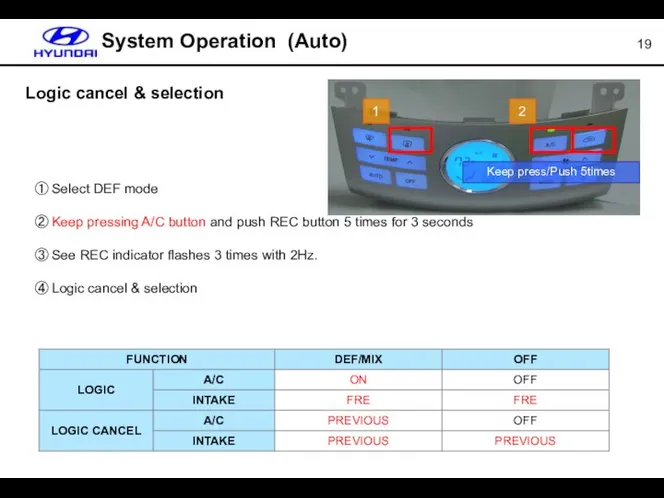
- 19. System Operation (Auto) Logic cancel & selection ① Select DEF mode ② Keep pressing A/C button
- 20. Temperature Unit Change * Setting unit: ℃ (Battery disconnection) * How to operate Keep pressing Press
- 21. Blower motor 1. Front blower motor - Capacity : 220W - Wheel size : Ø147 X
- 22. Compressor (Variable Swash Plate) Piston Swash plate Shaft Control chamber (Pc) Control Valve Inlet chamber (Ps)
- 23. HVAC (Heating, Ventilation and Air Conditioning) Components (Auto, Manual) MODE ACTUATOR HEATER CORE WATER TEMP SENSOR
- 24. HVAC (Heating, Ventilation and Air Conditioning) 2. Blower unit Components (Auto, Manual) INLET ACTUATOR AIR FILTER
- 25. Cooling Fan * Depending on the fuel type of the engine , Coolant temperature 'A' can
- 26. MOS FET (Metal Oxide Semiconductor Field Effect Transistor) Components (Auto) Vm Vds Blower motor Drain FET
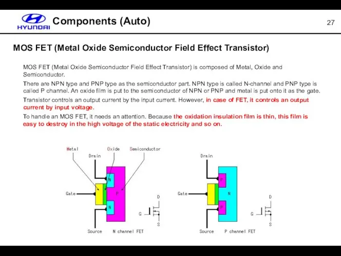
- 27. MOS FET (Metal Oxide Semiconductor Field Effect Transistor) Components (Auto) MOS FET (Metal Oxide Semiconductor Field
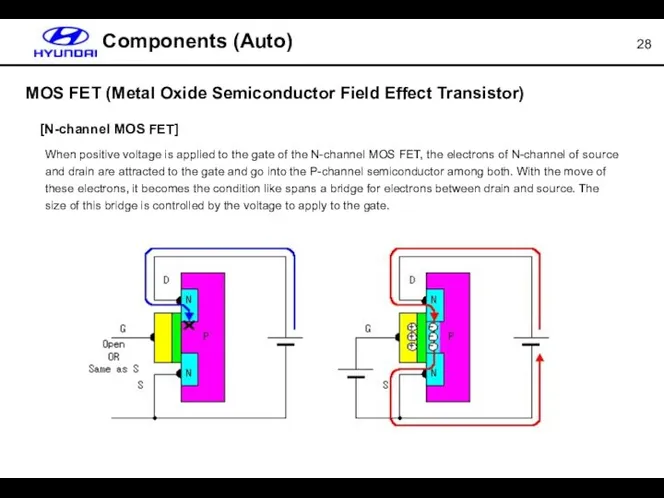
- 28. MOS FET (Metal Oxide Semiconductor Field Effect Transistor) Components (Auto) [N-channel MOS FET] When positive voltage
- 29. Components (Manual) Resistor
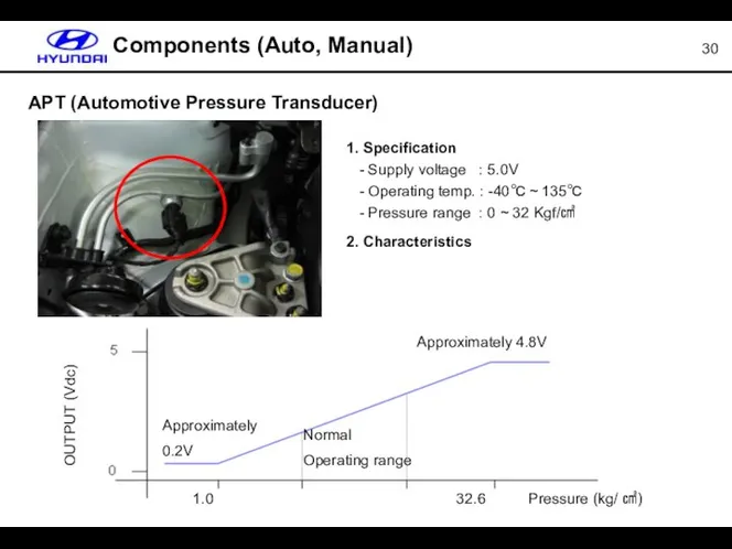
- 30. APT (Automotive Pressure Transducer) Components (Auto, Manual) 1. Specification - Supply voltage : 5.0V - Operating
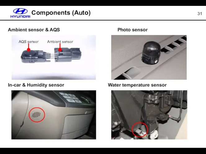
- 31. Components (Auto) Ambient sensor & AQS In-car & Humidity sensor Photo sensor Water temperature sensor AQS
- 32. Fresch air DEF DOOR VENT DOOR FOOT DOOR PTC Heater EVAPORATOR PTC HEATER HEATER CORE Heater
- 33. PTC Heater Engine ECM Heater/ Air conditioner Controller Relay # 1 Relay # 2 Relay #
- 34. PTC Heater PTC Heater operation condition * Engine rpm: Over 700 RPM * Ambient temperature :
- 35. PTC Heater Method - Mode: Vent, Bi-level or Floor - Temperature: Full warm (HI) - Blower
- 36. Failsafe (Manual) Failsafe mode
- 37. Failsafe (FATC) A/C sensor failsafe mode
- 38. Failsafe (FATC) DTC reading procedure Press AUTO Press AUTO Press OFF Press OFF Press mode 4
- 39. Failsafe (FATC) DTC list (Binary code displayed on the controller)
- 40. Failsafe (FATC) DTC list (Binary code displayed on the controller)
- 41. Hi-scan (current data) – 8 items Diagnosis
- 42. Hi-scan (Actuator test) Diagnosis
- 43. Hi-scan (Actuator test) Diagnosis
- 44. Diagnosis Hi-scan (Actuator test)
- 45. Diagnosis Hi-scan (Actuator test)
- 46. Intake door value change Diagnosis
- 48. Скачать презентацию
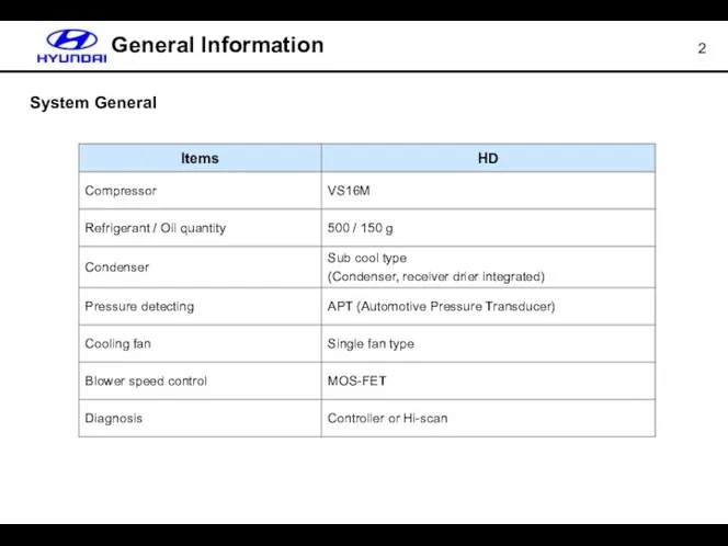
General Information
System General
General Information
System General
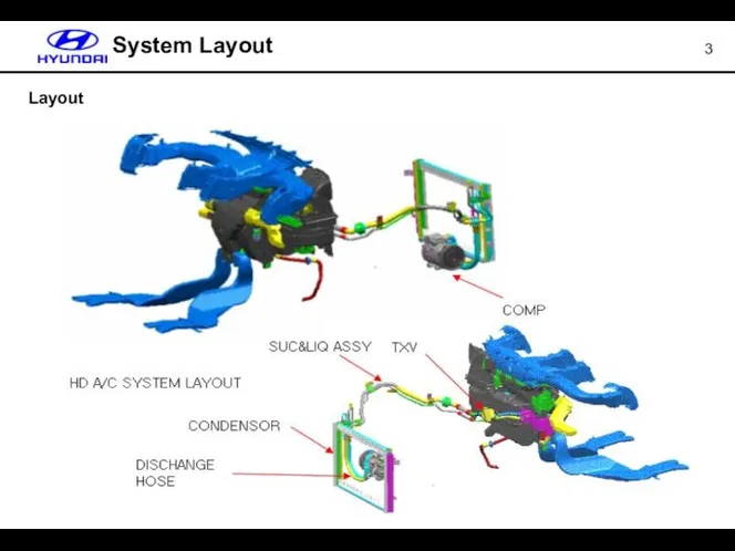
Layout
System Layout
Layout
System Layout
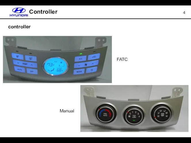
Controller
controller
FATC
Manual
Controller
controller
FATC
Manual
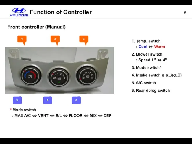
Function of Controller
1. Temp. switch : Cool ⬄ Warm
2. Blower switch
Function of Controller
1. Temp. switch : Cool ⬄ Warm
2. Blower switch
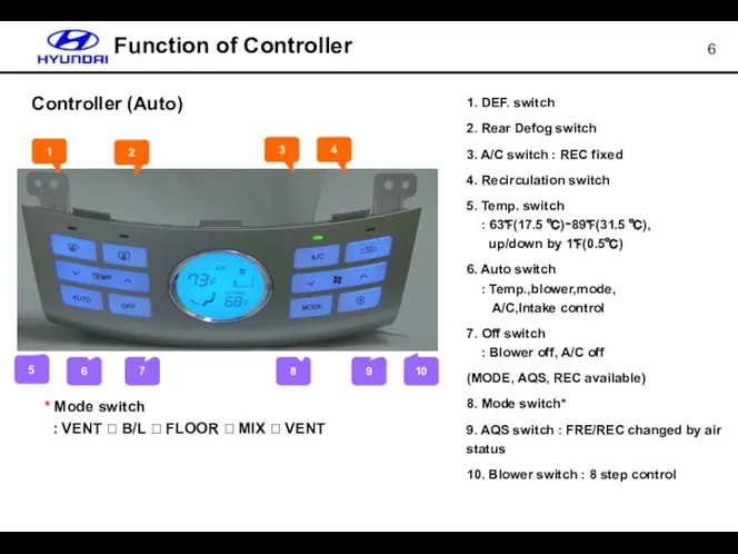
Function of Controller
Controller (Auto)
1. DEF. switch
2. Rear Defog switch
3. A/C
Function of Controller
Controller (Auto)
1. DEF. switch
2. Rear Defog switch
3. A/C
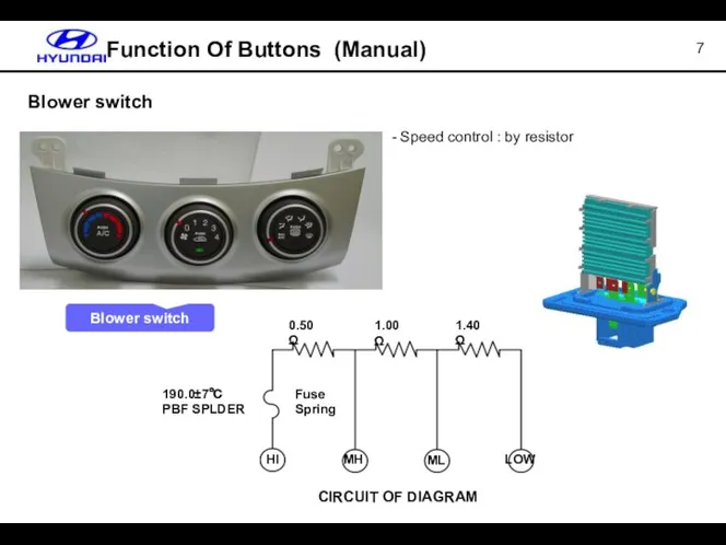
Blower switch
Function Of Buttons (Manual)
Speed control : by resistor
Blower switch
Blower switch
Function Of Buttons (Manual)
Speed control : by resistor
Blower switch
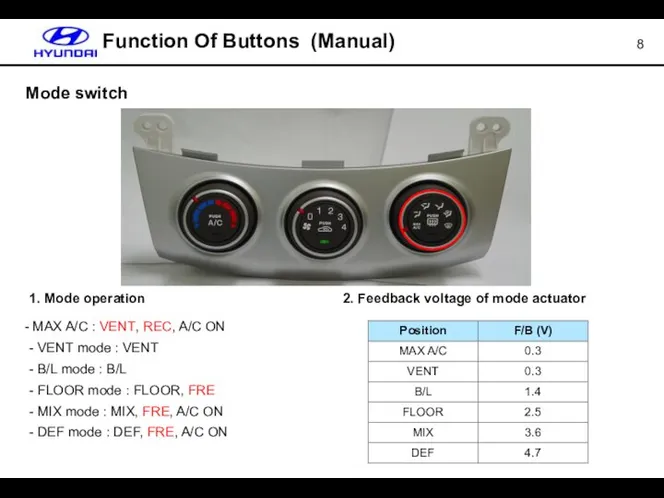
Mode switch
Function Of Buttons (Manual)
1. Mode operation
MAX A/C : VENT,
Mode switch
Function Of Buttons (Manual)
1. Mode operation
MAX A/C : VENT,
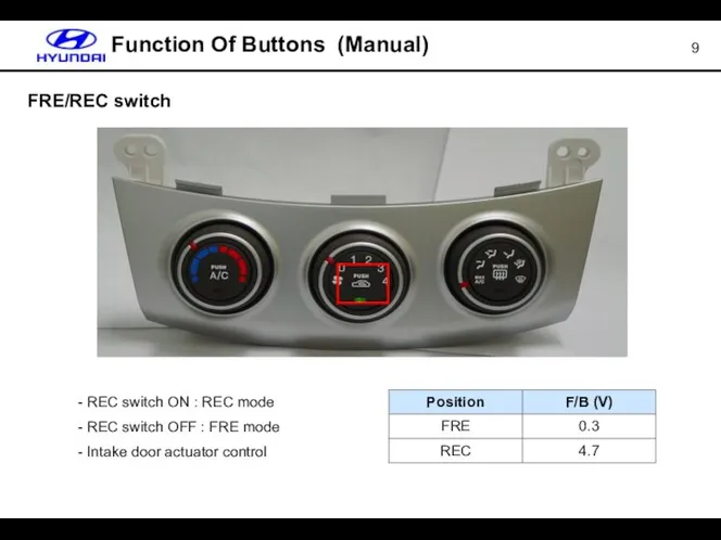
FRE/REC switch
Function Of Buttons (Manual)
REC switch ON : REC mode
FRE/REC switch
Function Of Buttons (Manual)
REC switch ON : REC mode
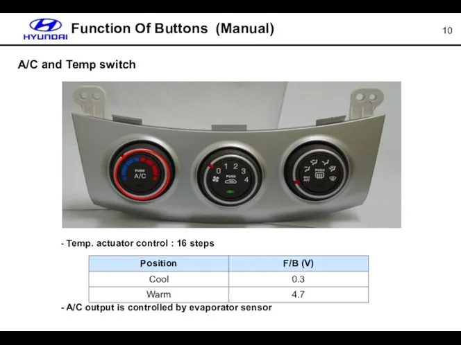
A/C and Temp switch
Function Of Buttons (Manual)
Temp. actuator control :
A/C and Temp switch
Function Of Buttons (Manual)
Temp. actuator control :
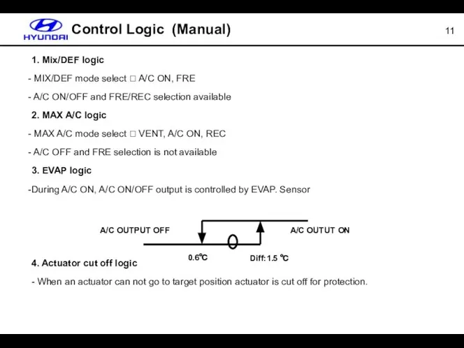
Control Logic (Manual)
1. Mix/DEF logic
MIX/DEF mode select ? A/C ON,
Control Logic (Manual)
1. Mix/DEF logic
MIX/DEF mode select ? A/C ON,
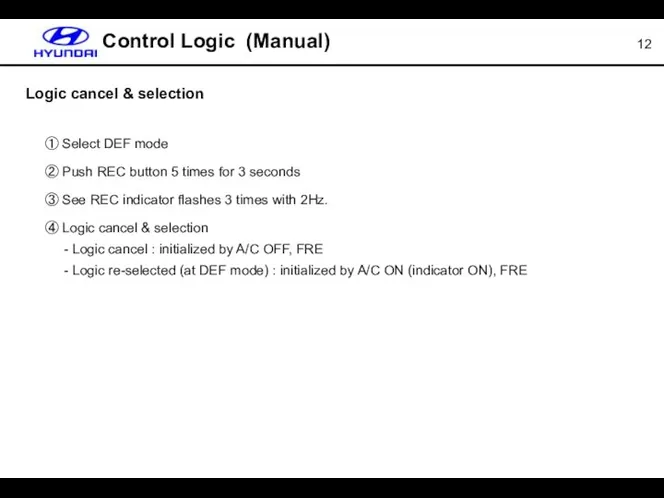
Logic cancel & selection
① Select DEF mode
② Push REC button 5
Logic cancel & selection
① Select DEF mode
② Push REC button 5
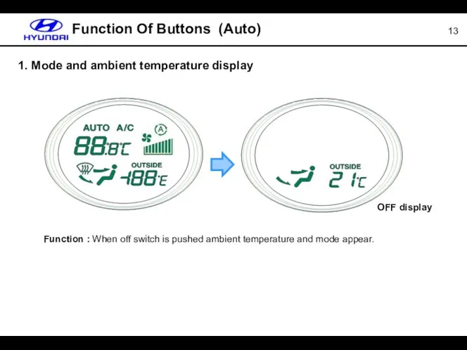
Function Of Buttons (Auto)
Function : When off switch is pushed
Function Of Buttons (Auto)
Function : When off switch is pushed
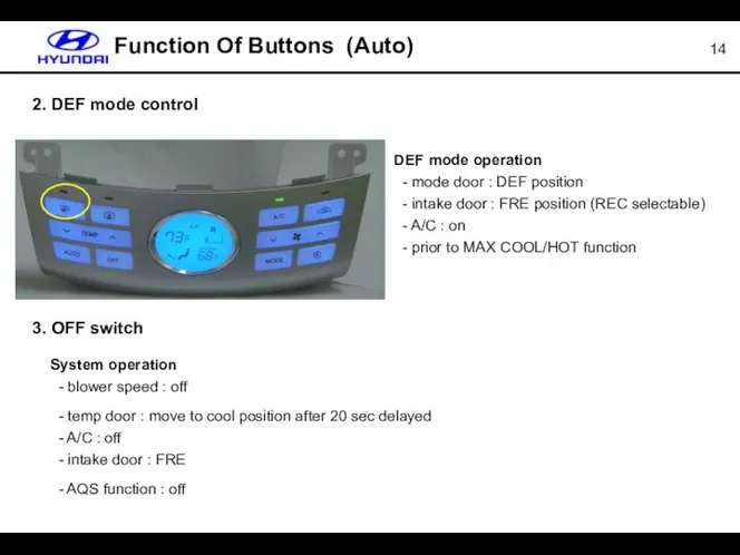
DEF mode operation
- mode door : DEF position
- intake
DEF mode operation - mode door : DEF position - intake
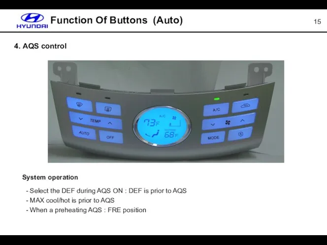
4. AQS control
Function Of Buttons (Auto)
System operation
- Select the DEF
4. AQS control
Function Of Buttons (Auto)
System operation
- Select the DEF
![5. Blower speed control System Operation (Auto) [Blower speed & motor voltage table]](/_ipx/f_webp&q_80&fit_contain&s_1440x1080/imagesDir/jpg/1489689/slide-15.jpg)
5. Blower speed control
System Operation (Auto)
[Blower speed & motor voltage table]
5. Blower speed control
System Operation (Auto)
[Blower speed & motor voltage table]
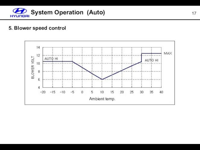
5. Blower speed control
System Operation (Auto)
Ambient temp.
5. Blower speed control
System Operation (Auto)
Ambient temp.
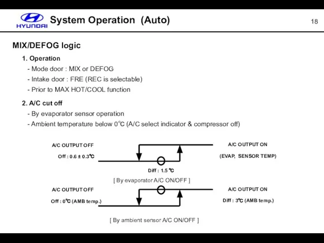
MIX/DEFOG logic
System Operation (Auto)
1. Operation
- Mode door : MIX or
MIX/DEFOG logic
System Operation (Auto)
1. Operation - Mode door : MIX or
System Operation (Auto)
Logic cancel & selection
① Select DEF mode
② Keep pressing
System Operation (Auto)
Logic cancel & selection
① Select DEF mode
② Keep pressing
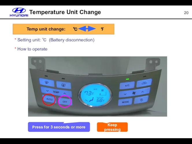
Temperature Unit Change
* Setting unit: ℃ (Battery disconnection)
* How to operate
Keep
Temperature Unit Change
* Setting unit: ℃ (Battery disconnection)
* How to operate
Keep
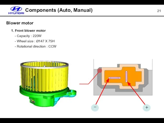
Blower motor
1. Front blower motor
- Capacity : 220W
- Wheel
Blower motor
1. Front blower motor - Capacity : 220W - Wheel
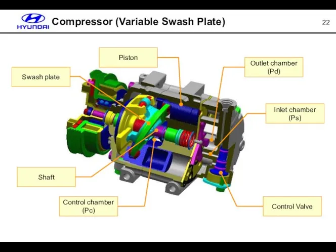
Compressor (Variable Swash Plate)
Piston
Swash plate
Shaft
Control chamber (Pc)
Control Valve
Inlet chamber (Ps)
Outlet chamber
Compressor (Variable Swash Plate)
Piston
Swash plate
Shaft
Control chamber (Pc)
Control Valve
Inlet chamber (Ps)
Outlet chamber
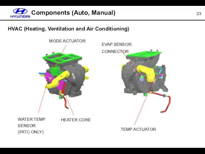
HVAC (Heating, Ventilation and Air Conditioning)
Components (Auto, Manual)
MODE ACTUATOR
HEATER CORE
WATER
HVAC (Heating, Ventilation and Air Conditioning)
Components (Auto, Manual)
MODE ACTUATOR
HEATER CORE
WATER
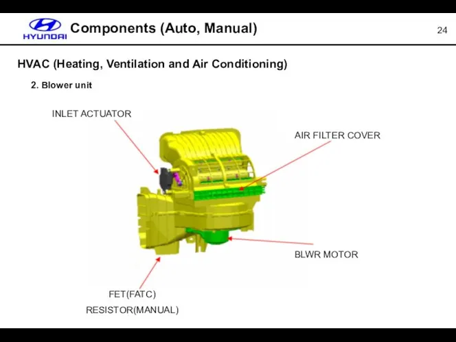
HVAC (Heating, Ventilation and Air Conditioning)
2. Blower unit
Components (Auto, Manual)
INLET
HVAC (Heating, Ventilation and Air Conditioning)
2. Blower unit
Components (Auto, Manual)
INLET
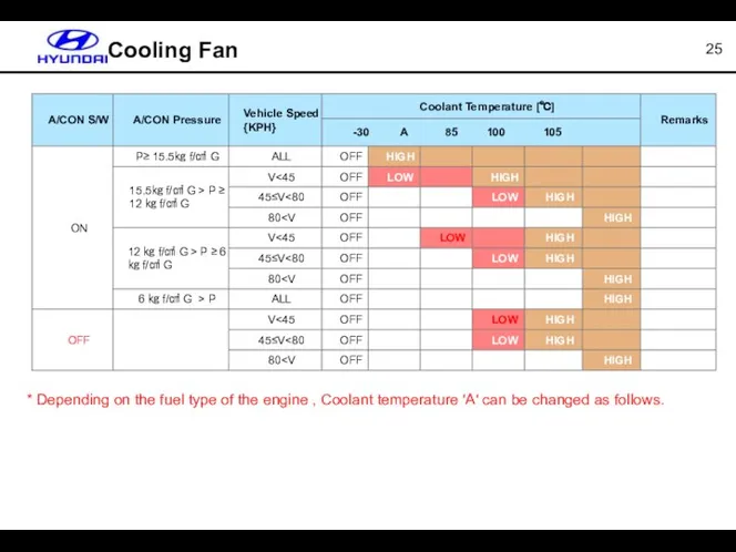
Cooling Fan
* Depending on the fuel type of the engine ,
Cooling Fan
* Depending on the fuel type of the engine ,
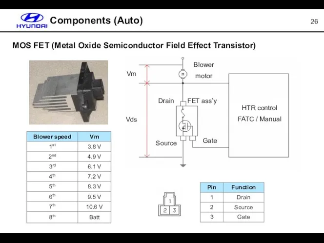
MOS FET (Metal Oxide Semiconductor Field Effect Transistor)
Components (Auto)
Vm
Vds
Blower
motor
Drain
FET ass’y
Source
Gate
HTR control
FATC
MOS FET (Metal Oxide Semiconductor Field Effect Transistor)
Components (Auto)
Vm
Vds
Blower
motor
Drain
FET ass’y
Source
Gate
HTR control
FATC
MOS FET (Metal Oxide Semiconductor Field Effect Transistor)
Components (Auto)
MOS FET (Metal
MOS FET (Metal Oxide Semiconductor Field Effect Transistor)
Components (Auto)
MOS FET (Metal
MOS FET (Metal Oxide Semiconductor Field Effect Transistor)
Components (Auto)
[N-channel MOS FET]
When
MOS FET (Metal Oxide Semiconductor Field Effect Transistor)
Components (Auto)
[N-channel MOS FET]
When
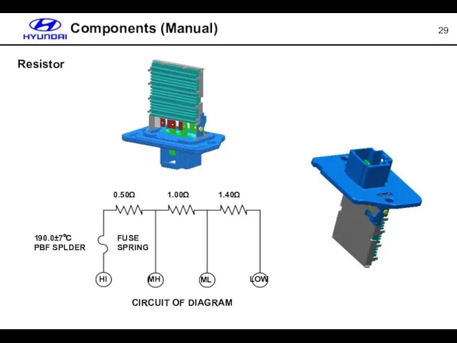
Components (Manual)
Resistor
Components (Manual)
Resistor
APT (Automotive Pressure Transducer)
Components (Auto, Manual)
1. Specification
- Supply voltage :
APT (Automotive Pressure Transducer)
Components (Auto, Manual)
1. Specification - Supply voltage :
Components (Auto)
Ambient sensor & AQS
In-car & Humidity sensor
Photo sensor
Water temperature sensor
AQS
Components (Auto)
Ambient sensor & AQS
In-car & Humidity sensor
Photo sensor
Water temperature sensor
AQS
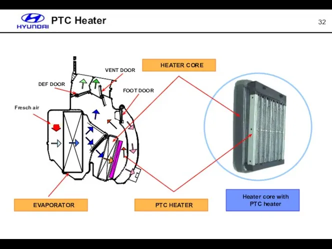
Fresch air
DEF DOOR
VENT DOOR
FOOT DOOR
PTC Heater
EVAPORATOR
PTC HEATER
HEATER CORE
Heater core with
PTC heater
Fresch air
DEF DOOR
VENT DOOR
FOOT DOOR
PTC Heater
EVAPORATOR
PTC HEATER
HEATER CORE
Heater core with
PTC heater
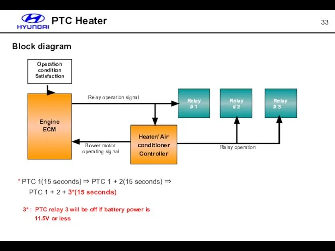
PTC Heater
Engine
ECM
Heater/ Air conditioner Controller
Relay
# 1
Relay
# 2
Relay
# 3
Relay operation
Blower motor
operating
PTC Heater
Engine
ECM
Heater/ Air conditioner Controller
Relay
# 1
Relay
# 2
Relay
# 3
Relay operation
Blower motor
operating
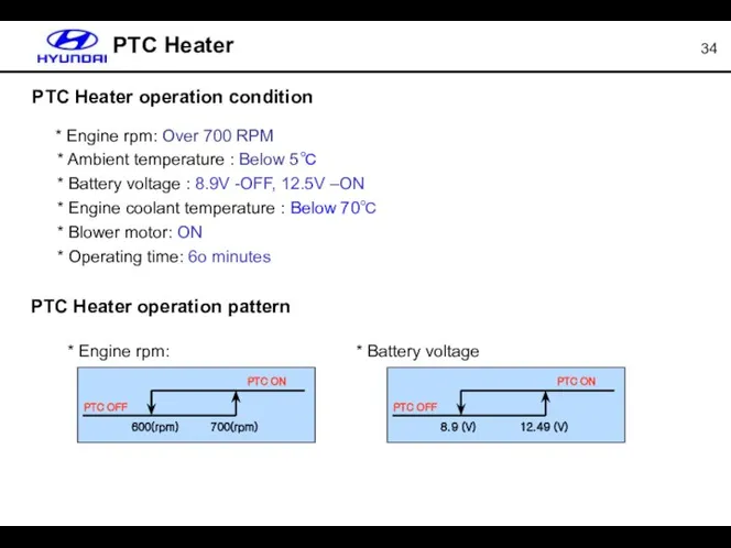
PTC Heater
PTC Heater operation condition
* Engine rpm: Over 700 RPM
*
PTC Heater
PTC Heater operation condition
* Engine rpm: Over 700 RPM
*
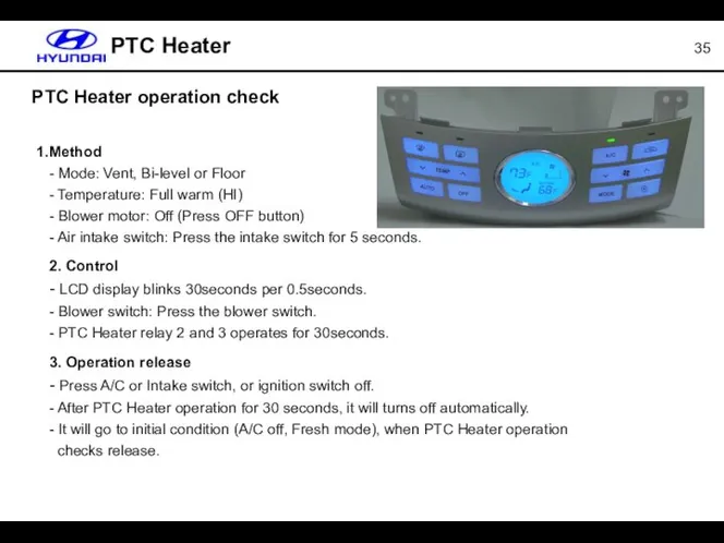
PTC Heater
Method
- Mode: Vent, Bi-level or Floor
- Temperature: Full warm (HI)
-
PTC Heater
Method - Mode: Vent, Bi-level or Floor - Temperature: Full warm (HI) -
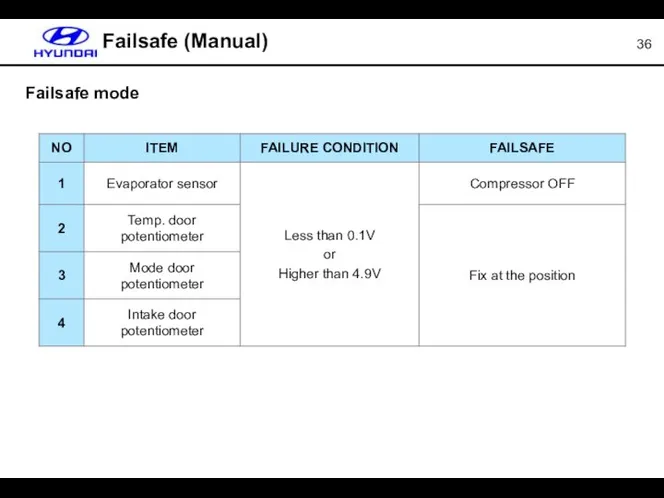
Failsafe (Manual)
Failsafe mode
Failsafe (Manual)
Failsafe mode
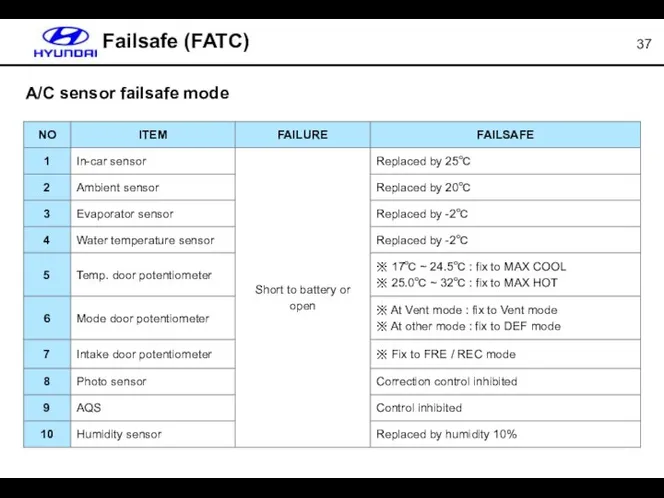
Failsafe (FATC)
A/C sensor failsafe mode
Failsafe (FATC)
A/C sensor failsafe mode
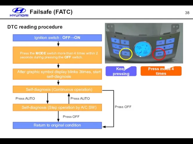
Failsafe (FATC)
DTC reading procedure
Press AUTO
Press AUTO
Press OFF
Press OFF
Press mode 4
Failsafe (FATC)
DTC reading procedure
Press AUTO
Press AUTO
Press OFF
Press OFF
Press mode 4
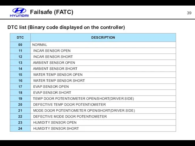
Failsafe (FATC)
DTC list (Binary code displayed on the controller)
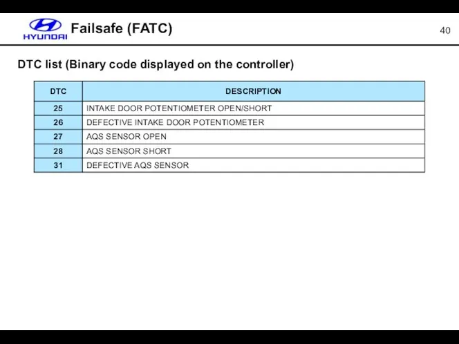
Failsafe (FATC)
DTC list (Binary code displayed on the controller)
Failsafe (FATC)
DTC list (Binary code displayed on the controller)
Failsafe (FATC)
DTC list (Binary code displayed on the controller)
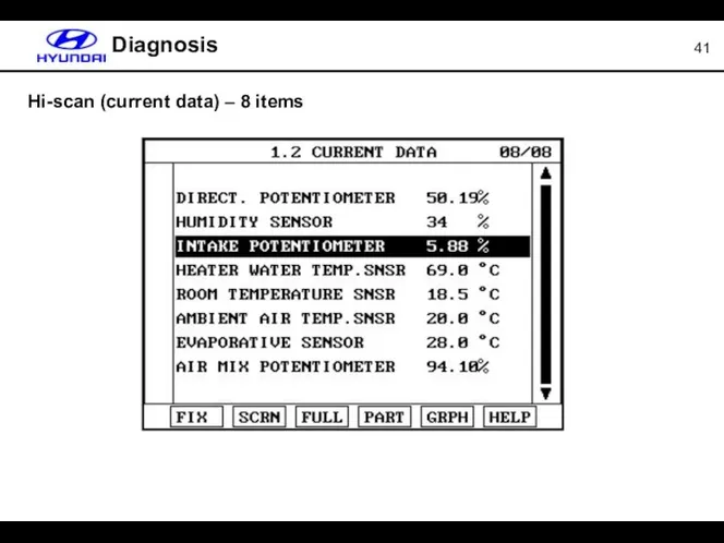
Hi-scan (current data) – 8 items
Diagnosis
Hi-scan (current data) – 8 items
Diagnosis
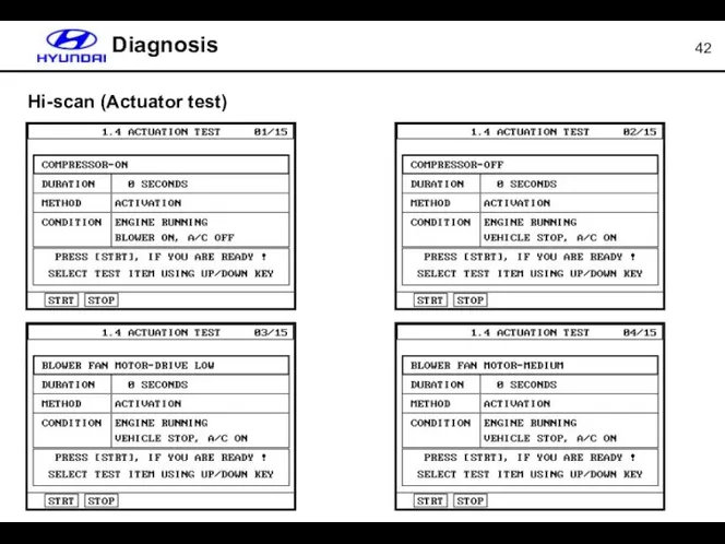
Hi-scan (Actuator test)
Diagnosis
Hi-scan (Actuator test)
Diagnosis
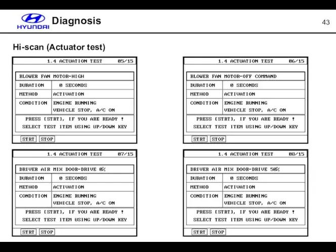
Hi-scan (Actuator test)
Diagnosis
Hi-scan (Actuator test)
Diagnosis
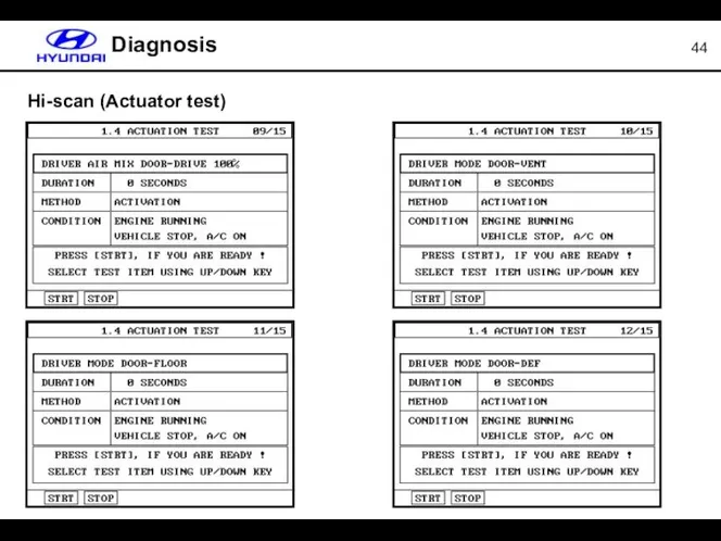
Diagnosis
Hi-scan (Actuator test)
Diagnosis
Hi-scan (Actuator test)
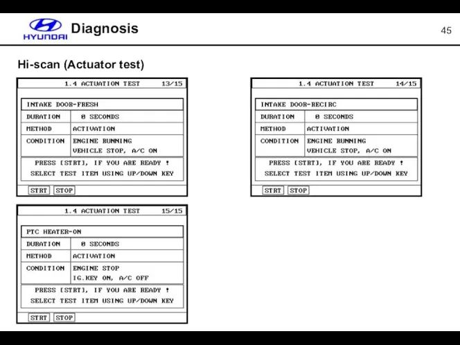
Diagnosis
Hi-scan (Actuator test)
Diagnosis
Hi-scan (Actuator test)
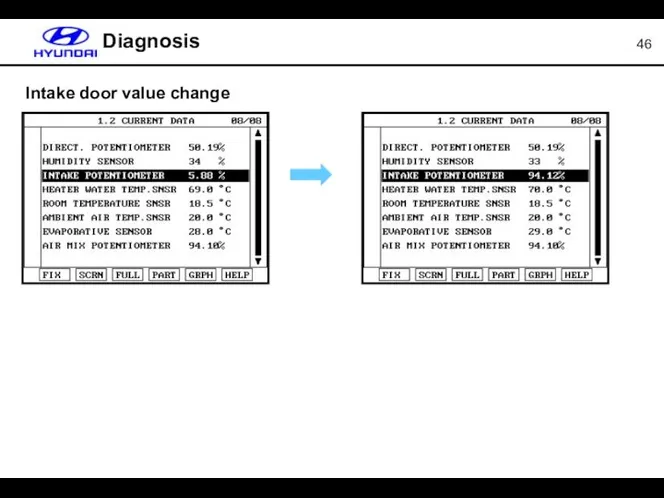
Intake door value change
Diagnosis
Intake door value change
Diagnosis
 Построение схемы к задаче. Дополнение текста к задаче - презентация для начальной школы
 Аутсорсинг персонала: складская логистика, производство, торговые сети
 Самоконтроль и самооценка на уроке физкультуры. Дневник самонаблюдения
 Структурна надійність
 Выйди из зоны комфорта. Книга 5
 Украина. Национальная культура
 История управленческой мысли
 Эффективный контракт и алгоритм его внедрения Механизм совершенствования системы оплаты труда, направленный на повышение эфф
 Организационно-правовая форма: учреждения
 Франція – визнаний туристичний бренд і лідер туризму Європейського макрорегіону (Лекція 8)
 Шаблоны информационных технологий как механизм реализации стратегии компании Николай Михайловский NTR Lab, Генеральный директор
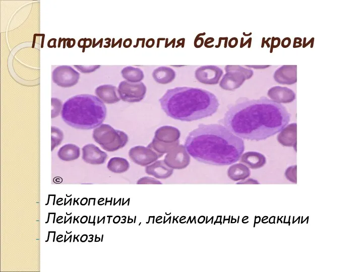 Патофизиология белой крови
 «История кредитной карты Урок по теме:
 Русско-немецкий центр встреч г. Котласа Архангельской области
 Методы экономических оценок альтернативных вариантов медицинской помощи
 Современные избирательные технологии
 Евангелическо-Лютеранская Церковь Христа Спасителя город Ижевск, Удмуртия
 Тайны омских кварталов Вводная презентация учителя
 Презентация по курсу «Основы информационных технологий» Руководитель: ст. преподаватель Воробьёв Михаил Алексеевич Выполнила:
  Дремучий медведь - презентация для начальной школы
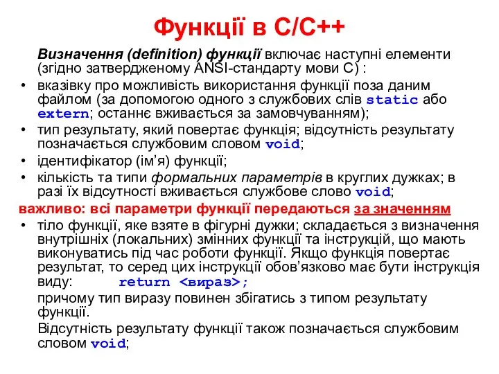 Функції в С/С++
 Об’єктивний контроль польотів авіації
 Концепции космологии
 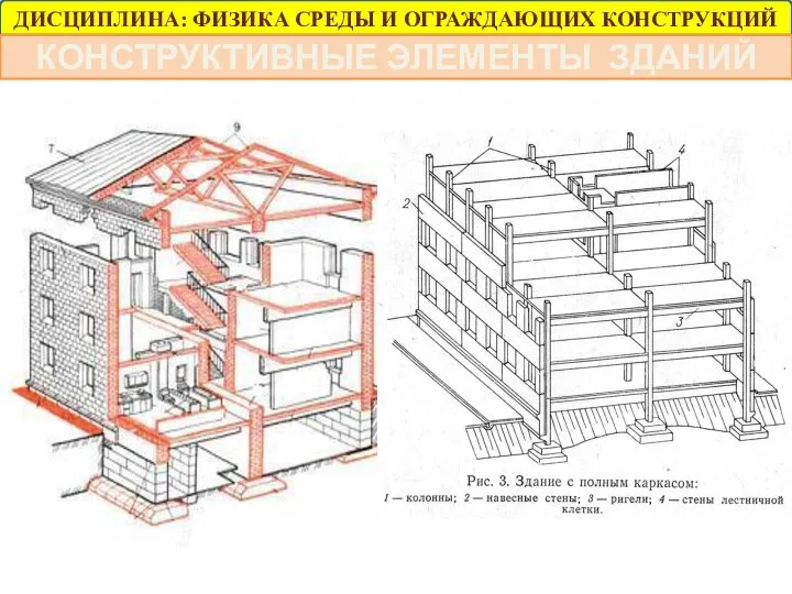 Конструктивные элементы зданий
 Роль кудо в физическом воспитании подрастающего поколения
 Выполнение расчетов по организации работ при строительстве и усилении дорог
 Презентация Применение экспортного тарифа Выполнили студенты 3 курса Орлова Л.А. и Овсянникова Н.С
 1)потоки внутриннихи внешних прямых иностранных инвестиций (то есть, сколько пришло в страну ПИИ) в 2010, 2011 и 2012; В долларах США в тек