- Internal Сombustion Engine. Fuel Systems. The carburetors

Содержание
- 2. Aleksey Terentyev Contact Information: Izhevsk State Technical University, 7 Studencheskaya street, Building 2, Room 415 426069,
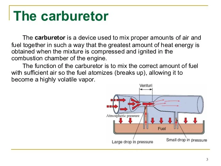
- 3. The carburetor The carburetor is a device used to mix proper amounts of air and fuel
- 4. When this vapor enters the combustion chamber of the engine and is compressed by the action
- 5. When the fuel and air are combined within the engine’s combustion chamber, a chemical balance is
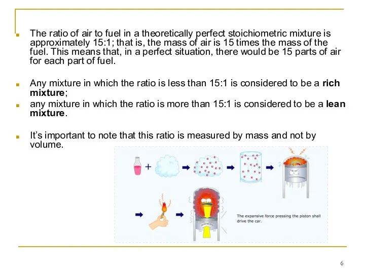
- 6. The ratio of air to fuel in a theoretically perfect stoichiometric mixture is approximately 15:1; that
- 7. Table lists the proper amounts of air and fuel, with regard to different engine running conditions
- 8. Gasoline is a liquid. Oxygen, on the other hand, is a gas and has the ability
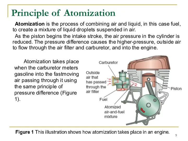
- 9. Principle of Atomization Atomization is the process of combining air and liquid, in this case fuel,
- 10. Figure 1 This illustration shows how atomization takes place in an engine. Atomization is the process
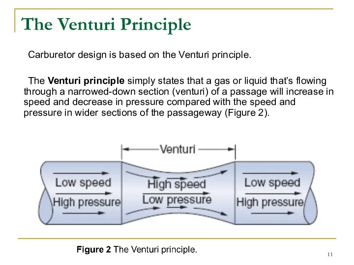
- 11. The Venturi Principle Carburetor design is based on the Venturi principle. The Venturi principle simply states
- 12. Figure 2 The Venturi principle. A venturi has a particular shape—a modified hourglass figure, you might
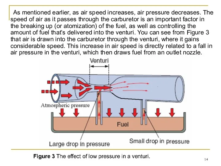
- 13. Figure 3 The effect of low pressure in a venturi. The major air passage in the
- 14. As mentioned earlier, as air speed increases, air pressure decreases. The speed of air as it
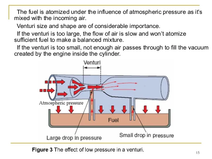
- 15. The fuel is atomized under the influence of atmospheric pressure as it’s mixed with the incoming
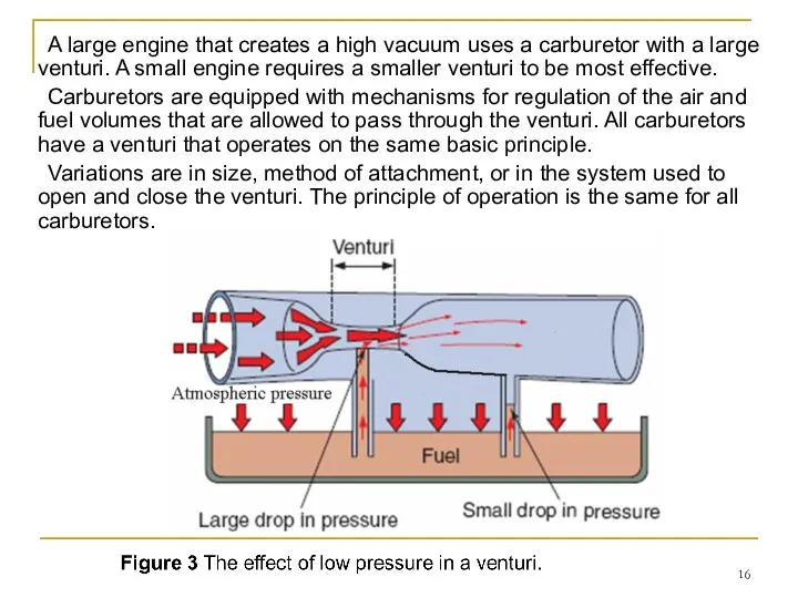
- 16. A large engine that creates a high vacuum uses a carburetor with a large venturi. A
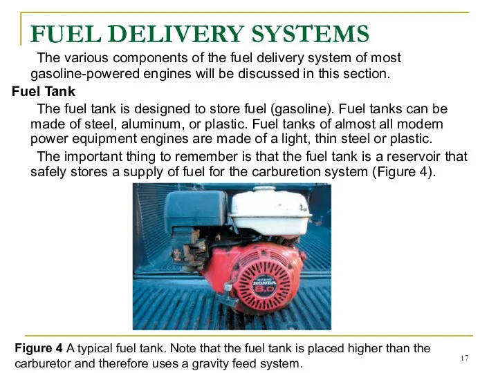
- 17. FUEL DELIVERY SYSTEMS The various components of the fuel delivery system of most gasoline-powered engines will
- 18. In many cases, the fuel tank uses a gravity feed system to allow fuel to flow
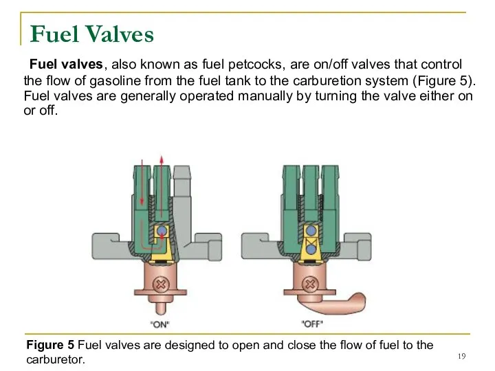
- 19. Fuel Valves Fuel valves, also known as fuel petcocks, are on/off valves that control the flow
- 20. Figure 5 Fuel valves are designed to open and close the flow of fuel to the
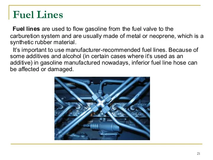
- 21. Fuel Lines Fuel lines are used to flow gasoline from the fuel valve to the carburetion
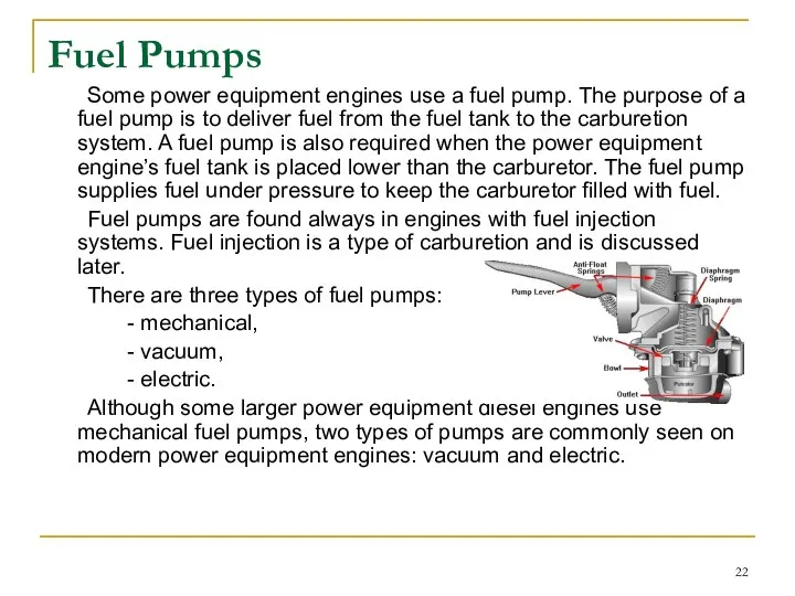
- 22. Fuel Pumps Some power equipment engines use a fuel pump. The purpose of a fuel pump
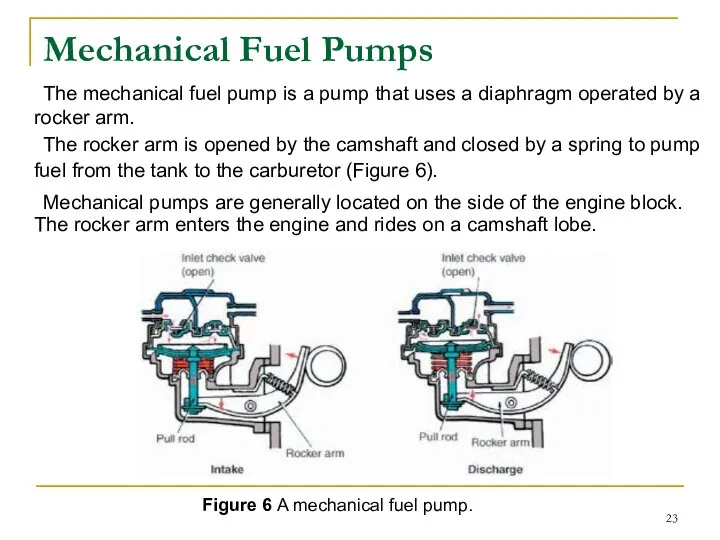
- 23. Mechanical Fuel Pumps The mechanical fuel pump is a pump that uses a diaphragm operated by
- 24. As the cam rotates, the rocker arm moves up and down. The lever is connected to
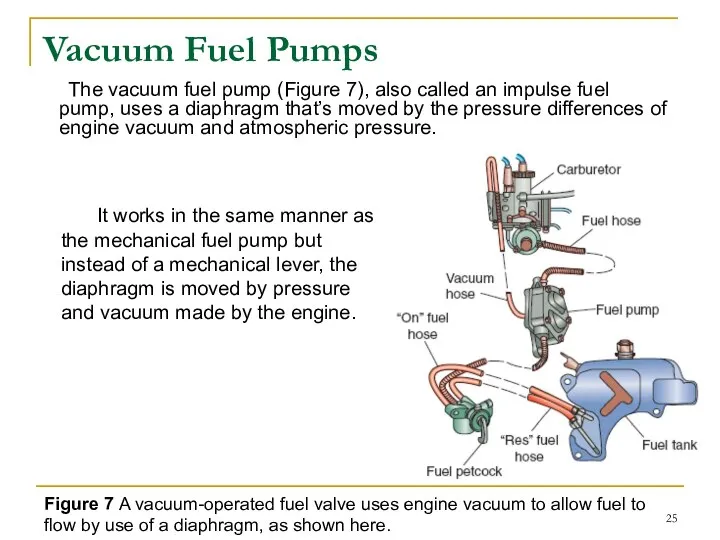
- 25. Vacuum Fuel Pumps The vacuum fuel pump (Figure 7), also called an impulse fuel pump, uses
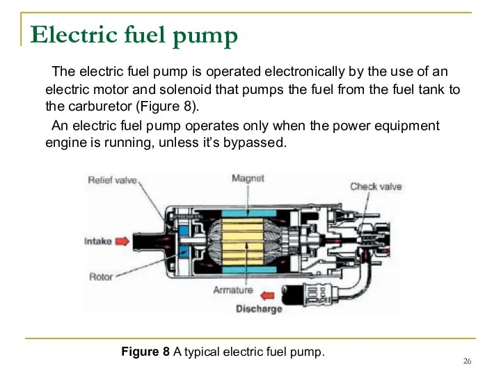
- 26. Electric fuel pump The electric fuel pump is operated electronically by the use of an electric
- 27. CARBURETOR TYPES AND OPERATION The carburetor has the task of combining the air and fuel into
- 28. Cold Start Systems For the cold start phase of engine operation, a rich fuel mixture is
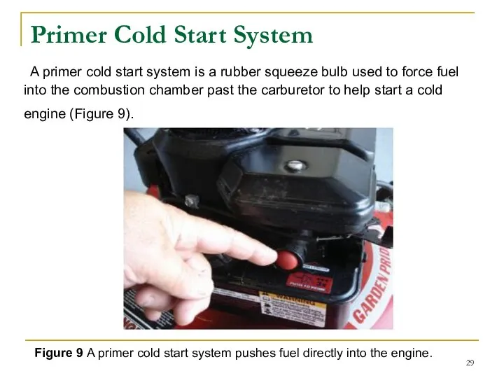
- 29. Primer Cold Start System A primer cold start system is a rubber squeeze bulb used to
- 30. There are two different types of the primer cold start system in power equipment engines: wet
- 31. Choke Plate Cold Start System The choke plate cold start system is an air restriction system
- 32. This plate has a small hole cut into it, a cut out in the plate, or
- 33. Choke Plate Operation The choke plate can be operated manually or by an automatic choke, as
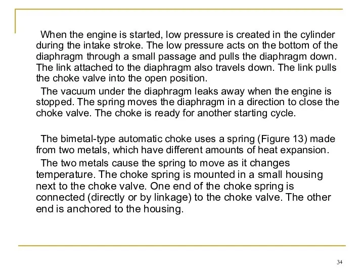
- 34. When the engine is started, low pressure is created in the cylinder during the intake stroke.
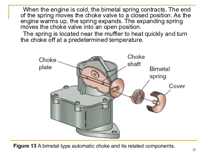
- 35. When the engine is cold, the bimetal spring contracts. The end of the spring moves the
- 36. Types of Carburetors There are many types of carburetor designs, but as you’ve learned, the fundamental
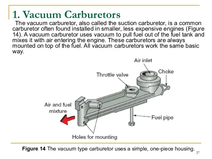
- 37. 1. Vacuum Carburetors The vacuum carburetor, also called the suction carburetor, is a common carburetor often
- 38. Figure 14 The vacuum type carburetor uses a simple, one-piece housing. A vacuum carburetor has a
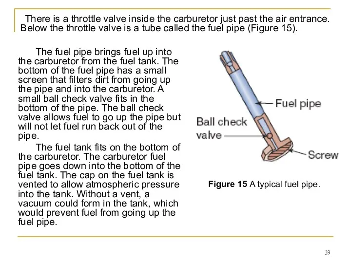
- 39. There is a throttle valve inside the carburetor just past the air entrance. Below the throttle
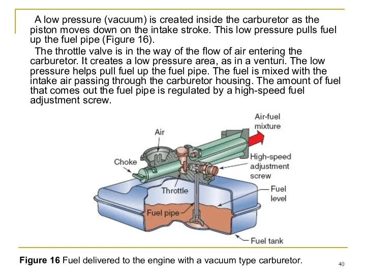
- 40. A low pressure (vacuum) is created inside the carburetor as the piston moves down on the
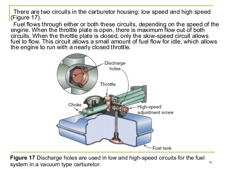
- 41. There are two circuits in the carburetor housing: low speed and high speed (Figure 17). Fuel
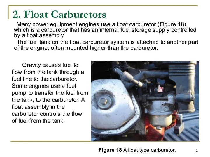
- 42. 2. Float Carburetors Many power equipment engines use a float carburetor (Figure 18), which is a
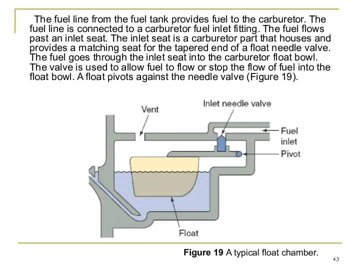
- 43. The fuel line from the fuel tank provides fuel to the carburetor. The fuel line is
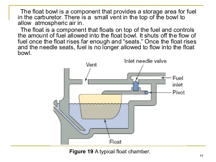
- 44. The float bowl is a component that provides a storage area for fuel in the carburetor.
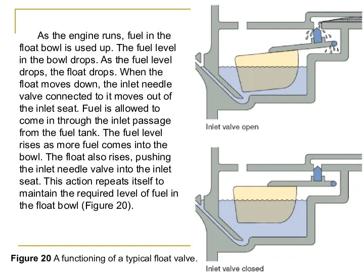
- 45. As the engine runs, fuel in the float bowl is used up. The fuel level in
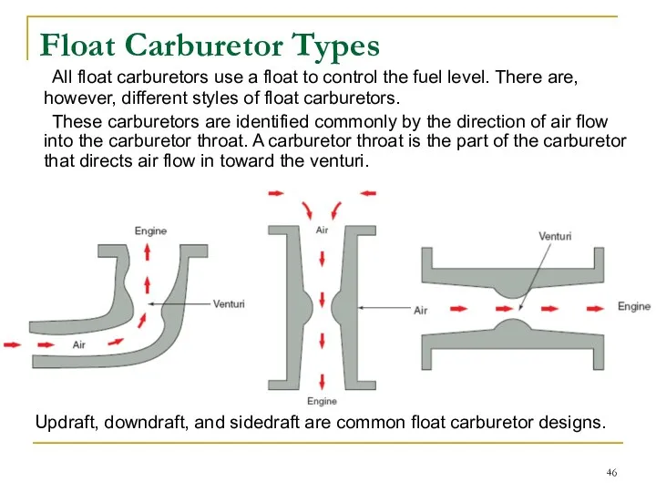
- 46. Float Carburetor Types All float carburetors use a float to control the fuel level. There are,
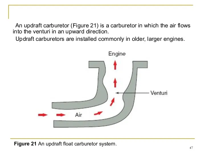
- 47. An updraft carburetor (Figure 21) is a carburetor in which the air flows into the venturi
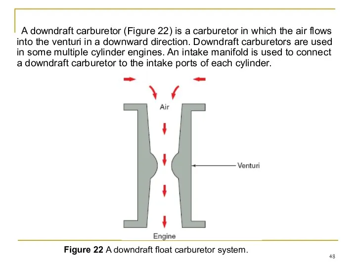
- 48. A downdraft carburetor (Figure 22) is a carburetor in which the air flows into the venturi
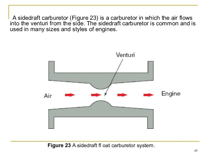
- 49. A sidedraft carburetor (Figure 23) is a carburetor in which the air flows into the venturi
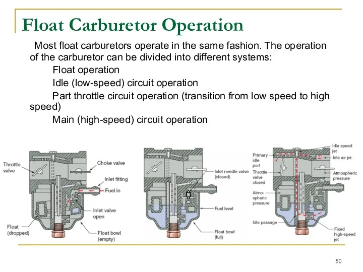
- 50. Float Carburetor Operation Most float carburetors operate in the same fashion. The operation of the carburetor
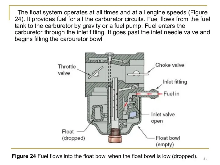
- 51. The float system operates at all times and at all engine speeds (Figure 24). It provides
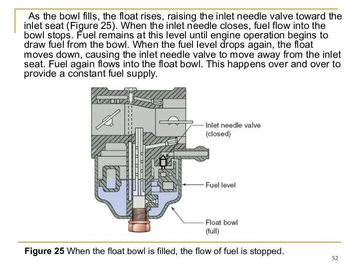
- 52. As the bowl fills, the float rises, raising the inlet needle valve toward the inlet seat
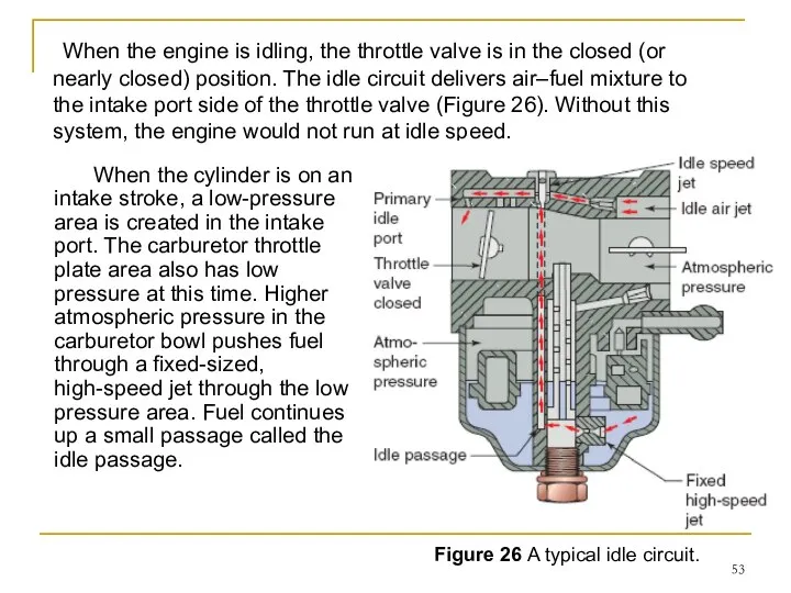
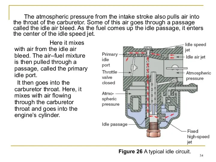
- 53. When the engine is idling, the throttle valve is in the closed (or nearly closed) position.
- 54. Here it mixes with air from the idle air bleed. The air–fuel mixture is then pulled
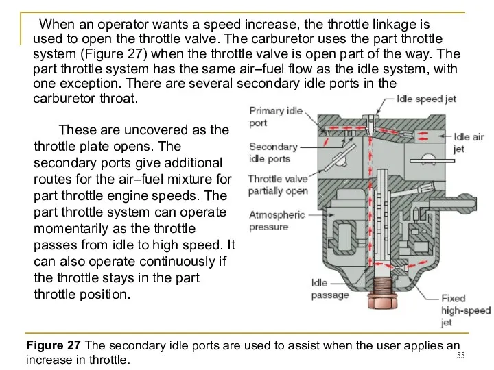
- 55. When an operator wants a speed increase, the throttle linkage is used to open the throttle
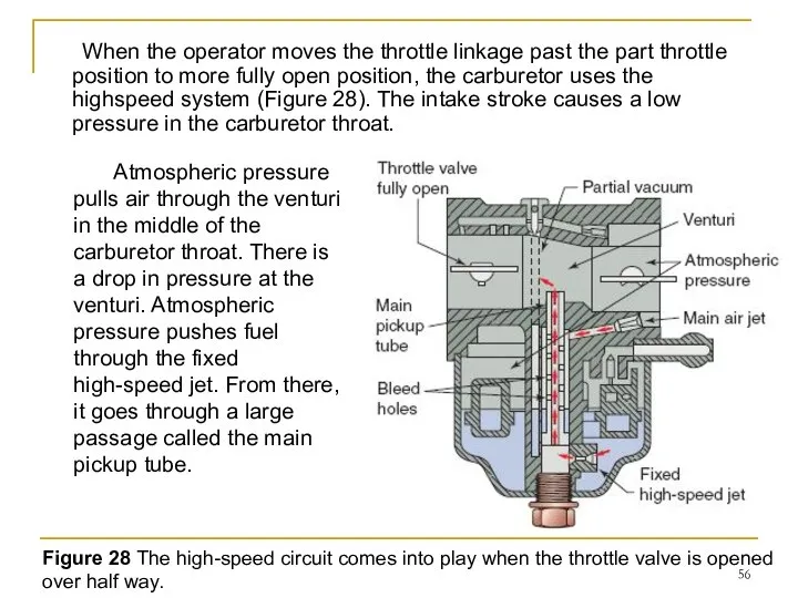
- 56. When the operator moves the throttle linkage past the part throttle position to more fully open
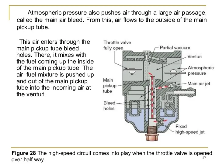
- 57. This air enters through the main pickup tube bleed holes. There, it mixes with the fuel
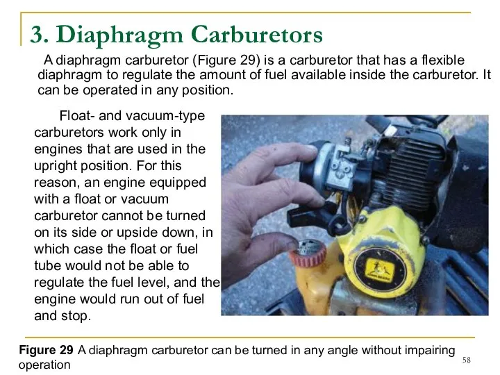
- 58. 3. Diaphragm Carburetors A diaphragm carburetor (Figure 29) is a carburetor that has a flexible diaphragm
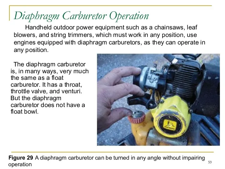
- 59. Diaphragm Carburetor Operation The diaphragm carburetor is, in many ways, very much the same as a
- 60. Figure 30 The parts of a diaphragm carburetor Instead, it uses a diaphragm similar to that
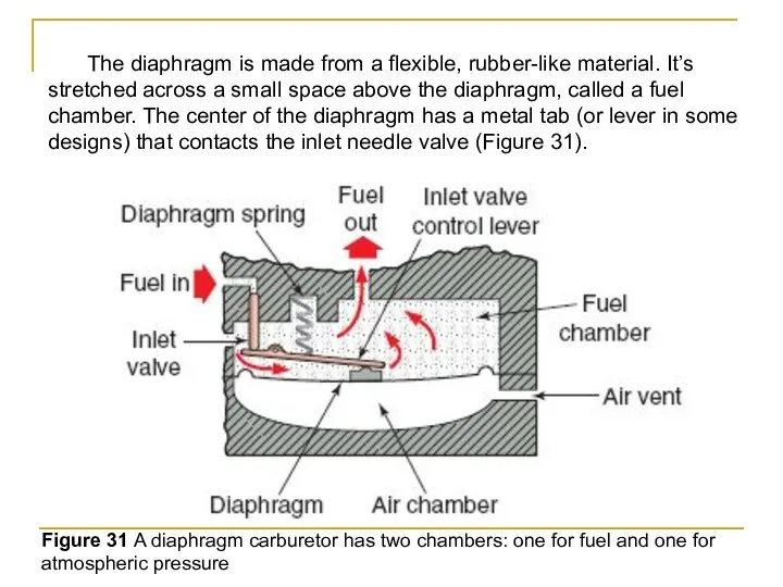
- 61. The diaphragm is made from a flexible, rubber-like material. It’s stretched across a small space above
- 62. Figure 31 A diaphragm carburetor has two chambers: one for fuel and one for atmospheric pressure
- 63. As fuel flows from the fuel tank to the fuel inlet, the spring pushes down on
- 64. Downward movement of the diaphragm causes the control lever to pivot upward. This movement pushes up
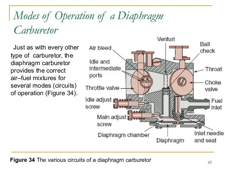
- 65. Modes of Operation of a Diaphragm Carburetor Just as with every other type of carburetor, the
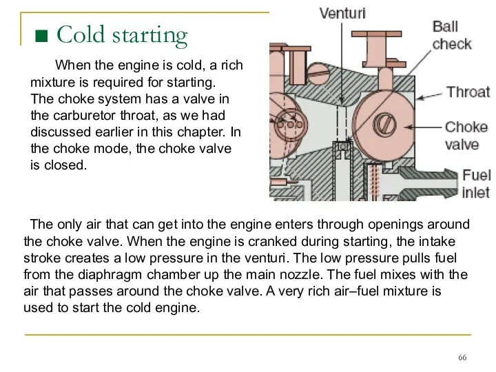
- 66. ■ Cold starting The only air that can get into the engine enters through openings around
- 67. During idle speeds, only a small amount of fuel is needed to keep the engine running.
- 68. When the throttle valve is moved past the idle position, it uncovers one more discharge port,
- 69. Fuel flows into the main nozzle through a passageway from the diaphragm chamber. Fuel going up
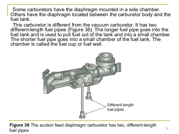
- 70. 4.Suction Feed Diaphragm Carburetors The suction feed diaphragm carburetor is a carburetor that combines the features
- 71. Some carburetors have the diaphragm mounted in a side chamber. Others have the diaphragm located between
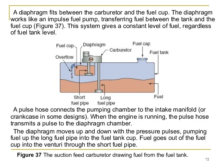
- 72. A diaphragm fits between the carburetor and the fuel cup. The diaphragm works like an impulse
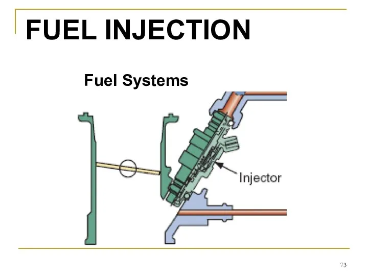
- 73. Fuel Systems FUEL INJECTION
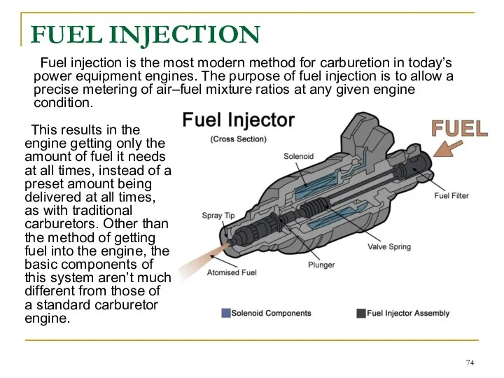
- 74. FUEL INJECTION Fuel injection is the most modern method for carburetion in today’s power equipment engines.
- 75. FUEL INJECTION In today’s power equipment engines, fuel injection is becoming popular as using it leads
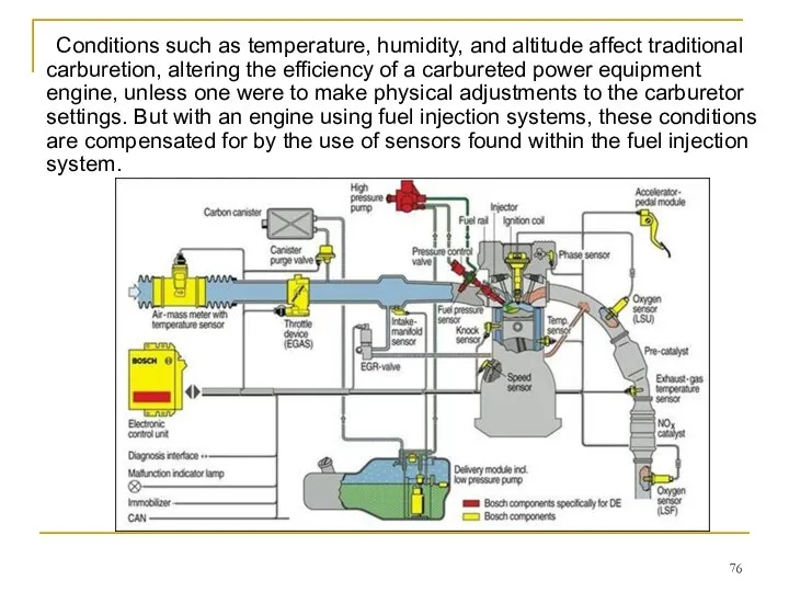
- 76. Conditions such as temperature, humidity, and altitude affect traditional carburetion, altering the efficiency of a carbureted
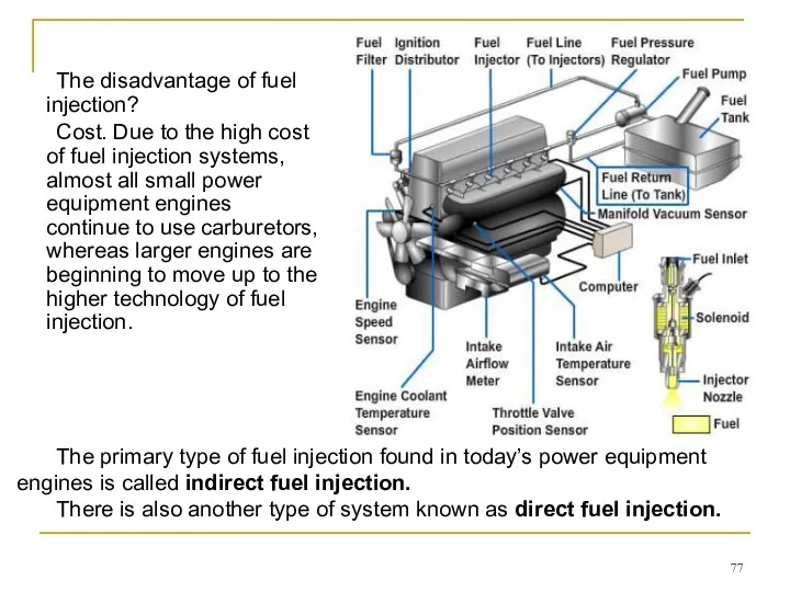
- 77. The disadvantage of fuel injection? Cost. Due to the high cost of fuel injection systems, almost
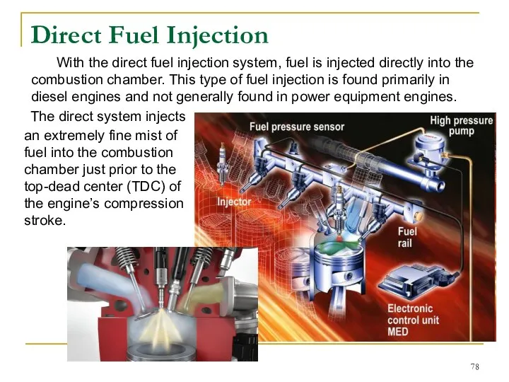
- 78. Direct Fuel Injection The direct system injects an extremely fine mist of fuel into the combustion
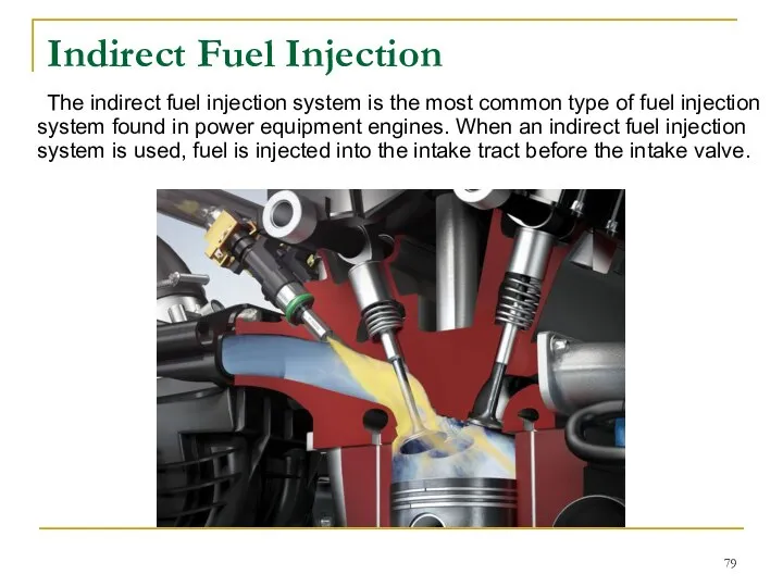
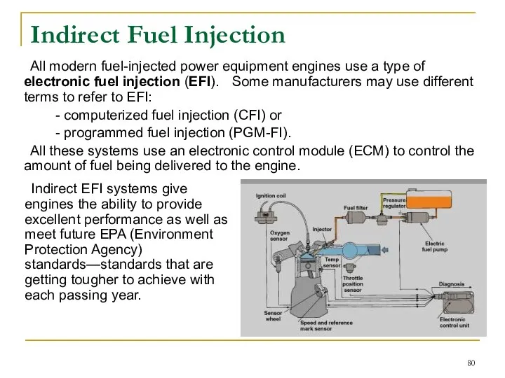
- 79. Indirect Fuel Injection The indirect fuel injection system is the most common type of fuel injection
- 80. Indirect Fuel Injection All modern fuel-injected power equipment engines use a type of electronic fuel injection
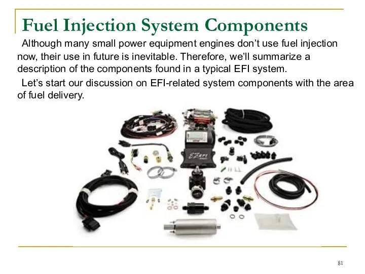
- 81. Fuel Injection System Сomponents Although many small power equipment engines don’t use fuel injection now, their
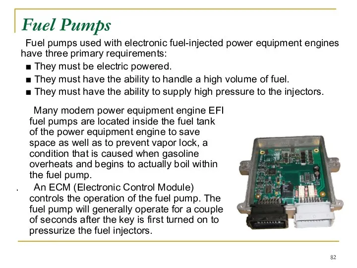
- 82. Fuel Pumps Fuel pumps used with electronic fuel-injected power equipment engines have three primary requirements: ■
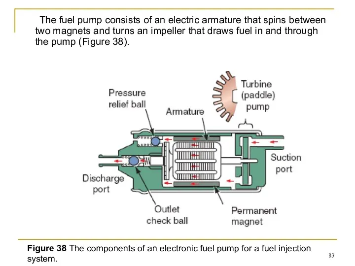
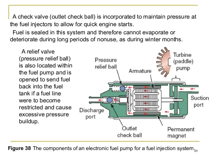
- 83. The fuel pump consists of an electric armature that spins between two magnets and turns an
- 84. A check valve (outlet check ball) is incorporated to maintain pressure at the fuel injectors to
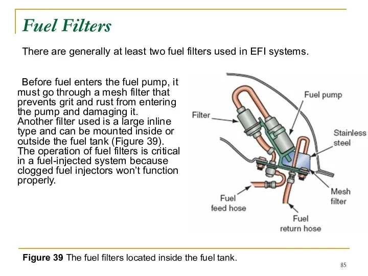
- 85. Fuel Filters Before fuel enters the fuel pump, it must go through a mesh filter that
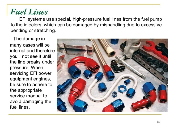
- 86. Fuel Lines The damage in many cases will be internal and therefore you’ll not see it
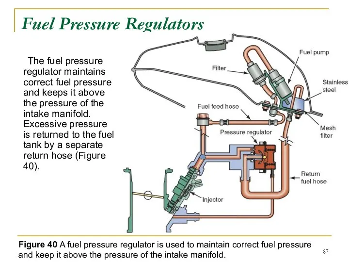
- 87. Fuel Pressure Regulators The fuel pressure regulator maintains correct fuel pressure and keeps it above the
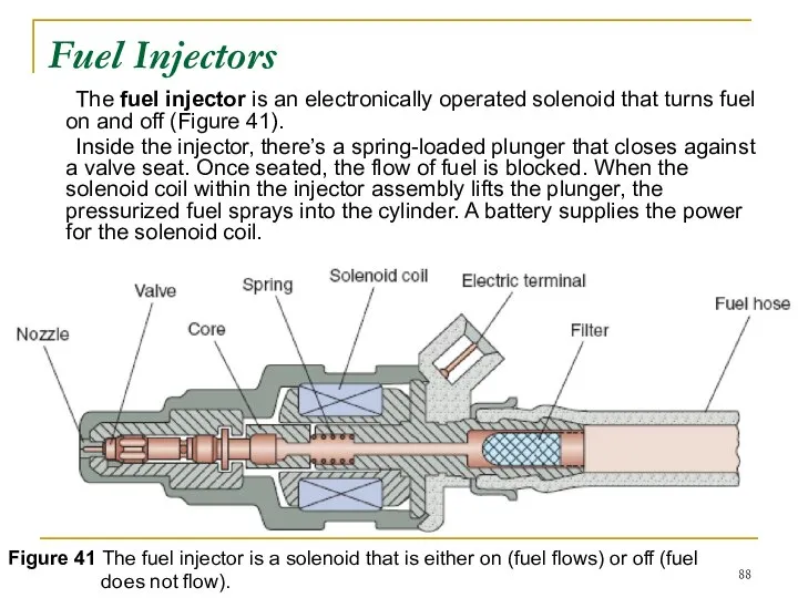
- 88. Fuel Injectors The fuel injector is an electronically operated solenoid that turns fuel on and off
- 89. The fuel injectors generally closed and are either fully closed or fully open. The ECM “tells”
- 90. Fuel injector tip openings are designed to provide a spray pattern that atomizes the fuel to
- 91. ECM The heart of all fuel injection systems is the ECM. The ECM receives signals from
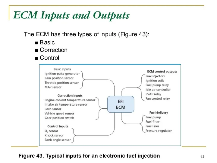
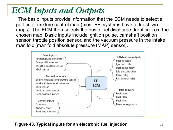
- 92. ECM Inputs and Outputs The ECM has three types of inputs (Figure 43): ■ Basic ■
- 93. ECM Inputs and Outputs The basic inputs provide information that the ECM needs to select a
- 94. The correction inputs provide the information that the ECM needs to adjust the basic fuel discharge
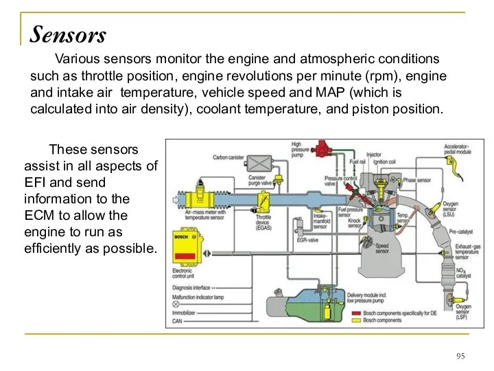
- 95. Various sensors monitor the engine and atmospheric conditions such as throttle position, engine revolutions per minute
- 96. Engines with EFI may have one throttle valve for each cylinder. The throttle body contains the
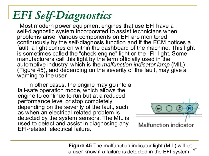
- 97. EFI Self-Diagnostics Most modern power equipment engines that use EFI have a self-diagnostic system incorporated to
- 98. Basic Operation of the Fuel Injection System In a typical EFI system, the ECM must “know”
- 99. Electronic feedback and closed loop Electronic feedback means the system is self-regulating and the ECM is
- 100. Control loops and catalytic converters When conditions such as starting or wideopen throttle demand that the
- 101. Summary ■ The primary principles of carburetor operation are atomization, the process of combining air and
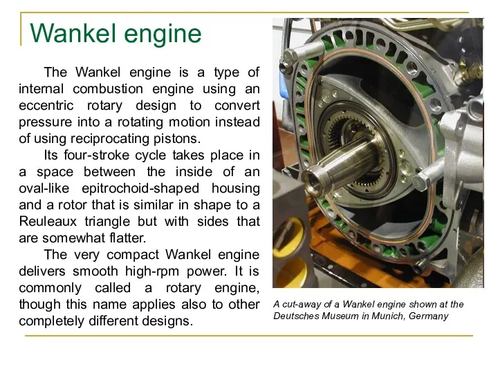
- 102. Wankel engine The Wankel engine is a type of internal combustion engine using an eccentric rotary
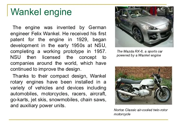
- 103. The engine was invented by German engineer Felix Wankel. He received his first patent for the
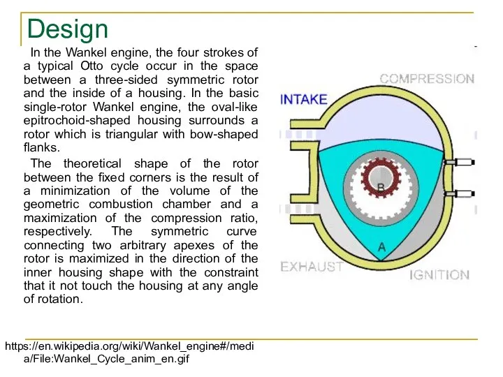
- 104. Design In the Wankel engine, the four strokes of a typical Otto cycle occur in the
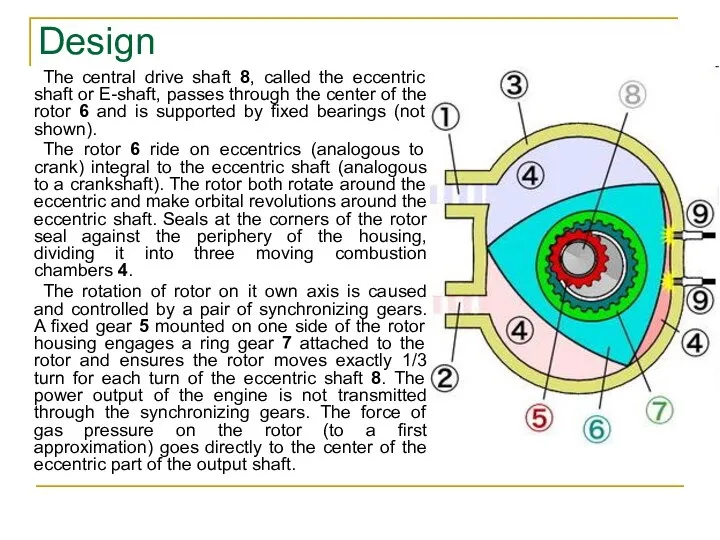
- 105. The central drive shaft 8, called the eccentric shaft or E-shaft, passes through the center of
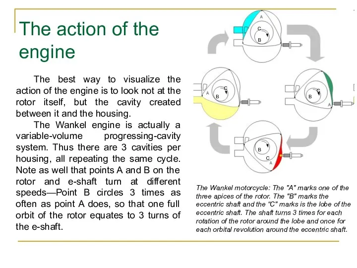
- 106. The best way to visualize the action of the engine is to look not at the
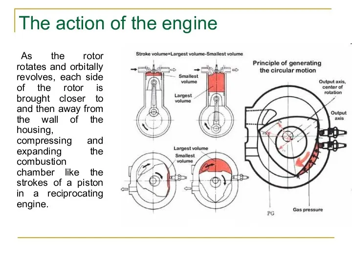
- 107. As the rotor rotates and orbitally revolves, each side of the rotor is brought closer to
- 108. While a four-stroke piston engine makes one combustion stroke per cylinder for every two rotations of
- 109. Wankel engines also generally have a much higher redline than a reciprocating engine of similar power
- 111. Скачать презентацию
Aleksey Terentyev
Contact Information:
Izhevsk State Technical University,
7 Studencheskaya street, Building
Aleksey Terentyev
Contact Information:
Izhevsk State Technical University,
7 Studencheskaya street, Building
The carburetor
The carburetor is a device used to mix proper amounts
The carburetor
The carburetor is a device used to mix proper amounts
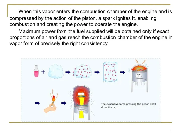
When this vapor enters the combustion chamber of the engine and
When this vapor enters the combustion chamber of the engine and
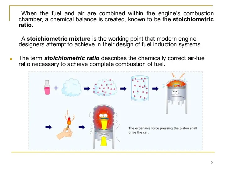
When the fuel and air are combined within the engine’s combustion
When the fuel and air are combined within the engine’s combustion
The ratio of air to fuel in a theoretically perfect stoichiometric
The ratio of air to fuel in a theoretically perfect stoichiometric
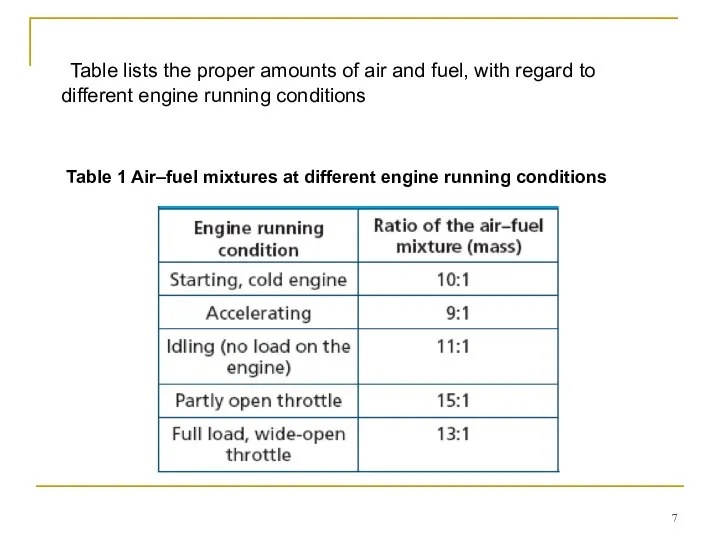
Table lists the proper amounts of air and fuel, with regard
Table lists the proper amounts of air and fuel, with regard
Gasoline is a liquid. Oxygen, on the other hand, is a
Gasoline is a liquid. Oxygen, on the other hand, is a
Principle of Atomization
Atomization is the process of combining air and liquid,
Principle of Atomization
Atomization is the process of combining air and liquid,
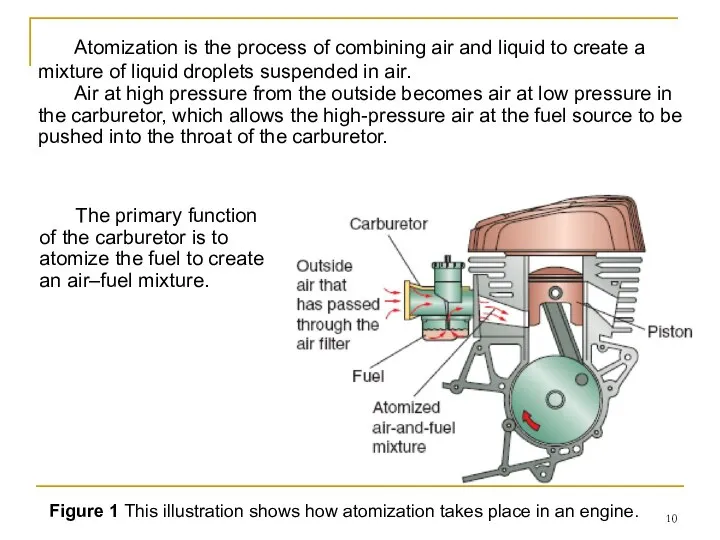
Figure 1 This illustration shows how atomization takes place in an
Figure 1 This illustration shows how atomization takes place in an
The Venturi Principle
Carburetor design is based on the Venturi principle.
The
The Venturi Principle
Carburetor design is based on the Venturi principle.
The
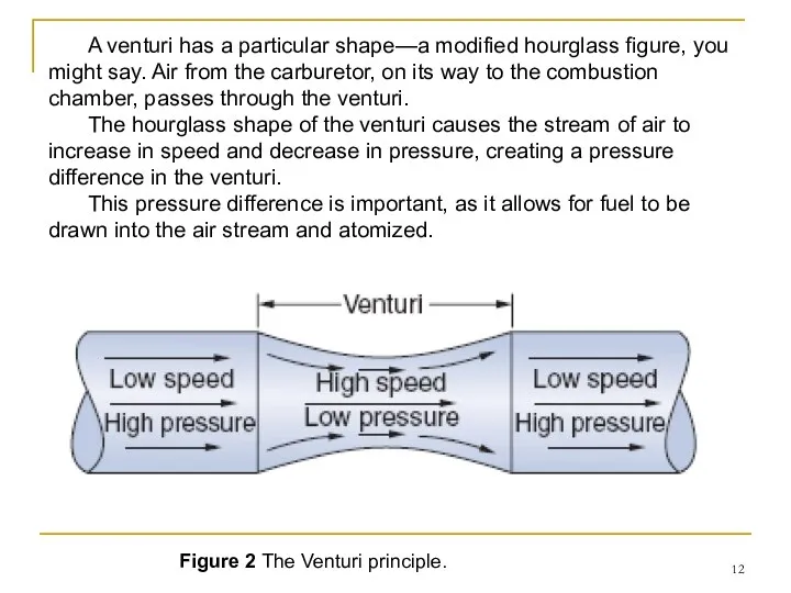
Figure 2 The Venturi principle.
A venturi has a particular shape—a modified
Figure 2 The Venturi principle.
A venturi has a particular shape—a modified
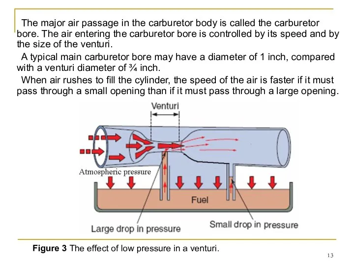
Figure 3 The effect of low pressure in a venturi.
The major
Figure 3 The effect of low pressure in a venturi.
The major
As mentioned earlier, as air speed increases, air pressure decreases. The
As mentioned earlier, as air speed increases, air pressure decreases. The
The fuel is atomized under the influence of atmospheric pressure as
The fuel is atomized under the influence of atmospheric pressure as
A large engine that creates a high vacuum uses a carburetor
A large engine that creates a high vacuum uses a carburetor
FUEL DELIVERY SYSTEMS
The various components of the fuel delivery system of
FUEL DELIVERY SYSTEMS
The various components of the fuel delivery system of
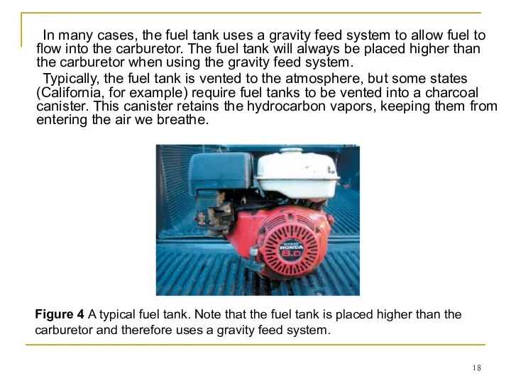
In many cases, the fuel tank uses a gravity feed system
In many cases, the fuel tank uses a gravity feed system
Fuel Valves
Fuel valves, also known as fuel petcocks, are on/off valves
Fuel Valves
Fuel valves, also known as fuel petcocks, are on/off valves
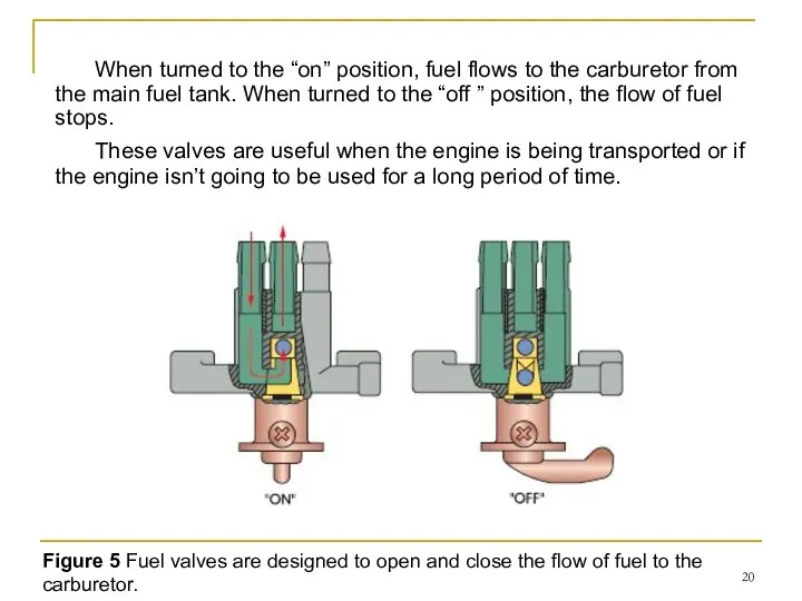
Figure 5 Fuel valves are designed to open and close the
Figure 5 Fuel valves are designed to open and close the
Fuel Lines
Fuel lines are used to flow gasoline from the fuel
Fuel Lines
Fuel lines are used to flow gasoline from the fuel
Fuel Pumps
Some power equipment engines use a fuel pump. The purpose
Fuel Pumps
Some power equipment engines use a fuel pump. The purpose
Mechanical Fuel Pumps
The mechanical fuel pump is a pump that uses
Mechanical Fuel Pumps
The mechanical fuel pump is a pump that uses
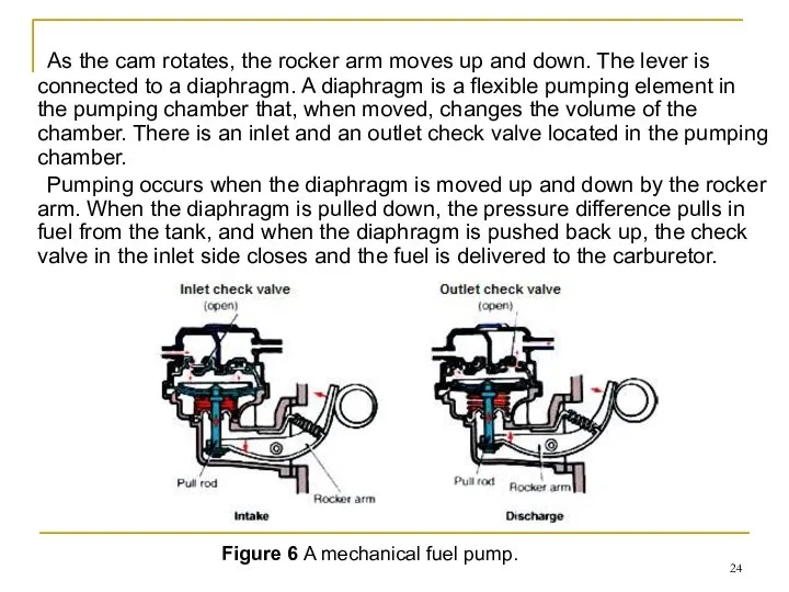
As the cam rotates, the rocker arm moves up and
As the cam rotates, the rocker arm moves up and
Vacuum Fuel Pumps
The vacuum fuel pump (Figure 7), also called an
Vacuum Fuel Pumps
The vacuum fuel pump (Figure 7), also called an
Electric fuel pump
The electric fuel pump is operated electronically by the
Electric fuel pump
The electric fuel pump is operated electronically by the
CARBURETOR TYPES AND
OPERATION
The carburetor has the task of combining the air
CARBURETOR TYPES AND
OPERATION
The carburetor has the task of combining the air
Cold Start Systems
For the cold start phase of engine operation, a
Cold Start Systems
For the cold start phase of engine operation, a
Primer Cold Start System
A primer cold start system is a rubber
Primer Cold Start System
A primer cold start system is a rubber
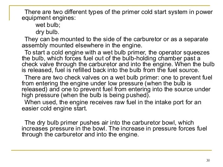
There are two different types of the primer cold start system
There are two different types of the primer cold start system
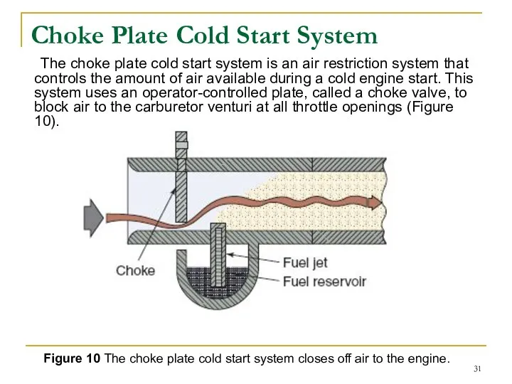
Choke Plate Cold Start System
The choke plate cold start system is
Choke Plate Cold Start System
The choke plate cold start system is
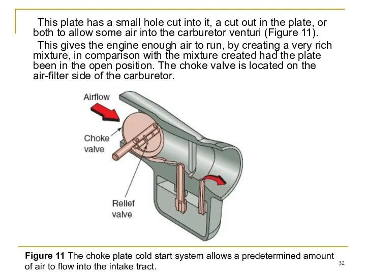
This plate has a small hole cut into it, a cut
This plate has a small hole cut into it, a cut
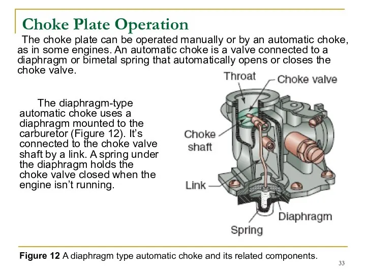
Choke Plate Operation
The choke plate can be operated manually or by
Choke Plate Operation
The choke plate can be operated manually or by
When the engine is started, low pressure is created in the
When the engine is started, low pressure is created in the
When the engine is cold, the bimetal spring contracts. The end
When the engine is cold, the bimetal spring contracts. The end
Types of Carburetors
There are many types of carburetor designs, but as
Types of Carburetors
There are many types of carburetor designs, but as
1. Vacuum Carburetors
The vacuum carburetor, also called the suction carburetor, is
1. Vacuum Carburetors
The vacuum carburetor, also called the suction carburetor, is
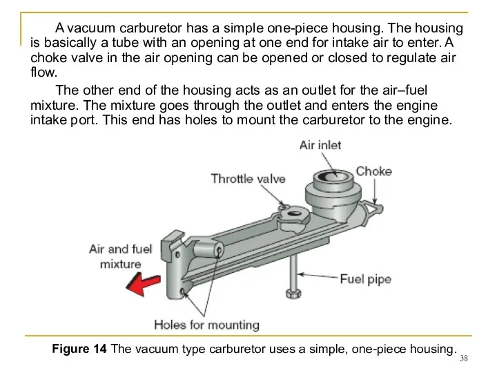
Figure 14 The vacuum type carburetor uses a simple, one-piece housing.
A
Figure 14 The vacuum type carburetor uses a simple, one-piece housing.
A
There is a throttle valve inside the carburetor just past the
There is a throttle valve inside the carburetor just past the
A low pressure (vacuum) is created inside the carburetor as the
A low pressure (vacuum) is created inside the carburetor as the
There are two circuits in the carburetor housing: low speed and
There are two circuits in the carburetor housing: low speed and
2. Float Carburetors
Many power equipment engines use a float carburetor (Figure
2. Float Carburetors
Many power equipment engines use a float carburetor (Figure
The fuel line from the fuel tank provides fuel to the
The fuel line from the fuel tank provides fuel to the
The float bowl is a component that provides a storage area
The float bowl is a component that provides a storage area
As the engine runs, fuel in the float bowl is used
As the engine runs, fuel in the float bowl is used
Float Carburetor Types
All float carburetors use a float to control the
Float Carburetor Types
All float carburetors use a float to control the
An updraft carburetor (Figure 21) is a carburetor in which the
An updraft carburetor (Figure 21) is a carburetor in which the
A downdraft carburetor (Figure 22) is a carburetor in which the
A downdraft carburetor (Figure 22) is a carburetor in which the
A sidedraft carburetor (Figure 23) is a carburetor in which the
A sidedraft carburetor (Figure 23) is a carburetor in which the
Float Carburetor Operation
Most float carburetors operate in the same fashion. The
Float Carburetor Operation
Most float carburetors operate in the same fashion. The
The float system operates at all times and at all engine
The float system operates at all times and at all engine
As the bowl fills, the float rises, raising the inlet needle
As the bowl fills, the float rises, raising the inlet needle
When the engine is idling, the throttle valve is in the
When the engine is idling, the throttle valve is in the
Here it mixes with air from the idle air bleed. The
Here it mixes with air from the idle air bleed. The
When an operator wants a speed increase, the throttle linkage is
When an operator wants a speed increase, the throttle linkage is
When the operator moves the throttle linkage past the part throttle
When the operator moves the throttle linkage past the part throttle
This air enters through the main pickup tube bleed holes. There,
This air enters through the main pickup tube bleed holes. There,
3. Diaphragm Carburetors
A diaphragm carburetor (Figure 29) is a carburetor that
3. Diaphragm Carburetors
A diaphragm carburetor (Figure 29) is a carburetor that
Diaphragm Carburetor Operation
The diaphragm carburetor is, in many ways, very much
Diaphragm Carburetor Operation
The diaphragm carburetor is, in many ways, very much
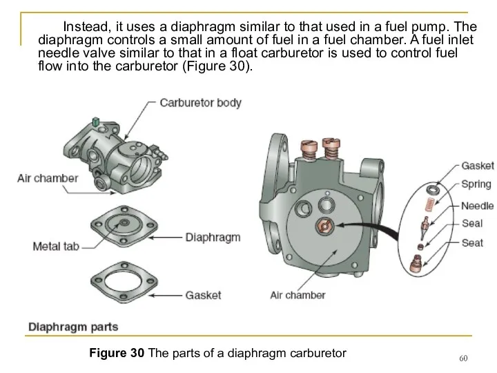
Figure 30 The parts of a diaphragm carburetor
Instead, it uses a
Figure 30 The parts of a diaphragm carburetor
Instead, it uses a
The diaphragm is made from a flexible, rubber-like material. It’s stretched
The diaphragm is made from a flexible, rubber-like material. It’s stretched

Figure 31 A diaphragm carburetor has two chambers: one for fuel
Figure 31 A diaphragm carburetor has two chambers: one for fuel
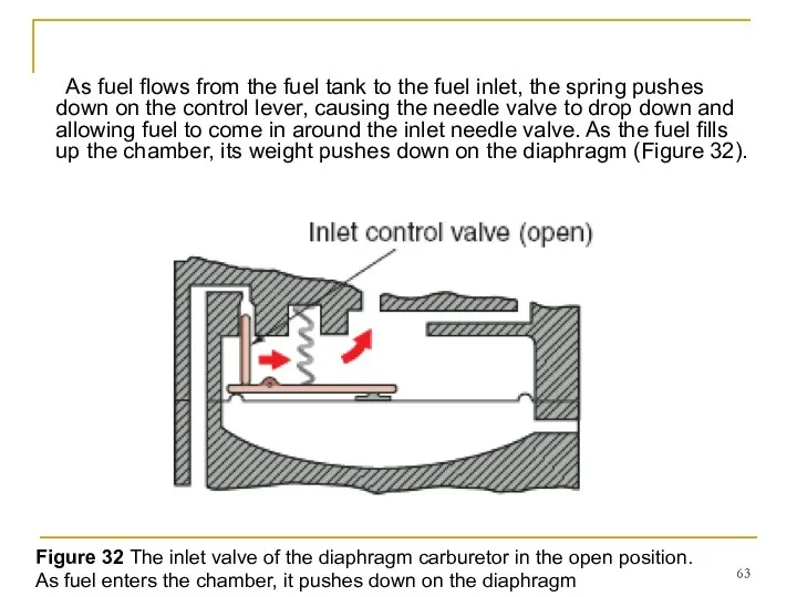
As fuel flows from the fuel tank to the fuel inlet,
As fuel flows from the fuel tank to the fuel inlet,
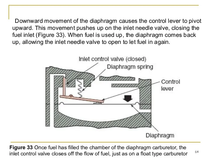
Downward movement of the diaphragm causes the control lever to pivot
Downward movement of the diaphragm causes the control lever to pivot
Modes of Operation of a Diaphragm
Carburetor
Just as with every other type
Modes of Operation of a Diaphragm
Carburetor
Just as with every other type
■ Cold starting
The only air that can get into the engine
■ Cold starting
The only air that can get into the engine
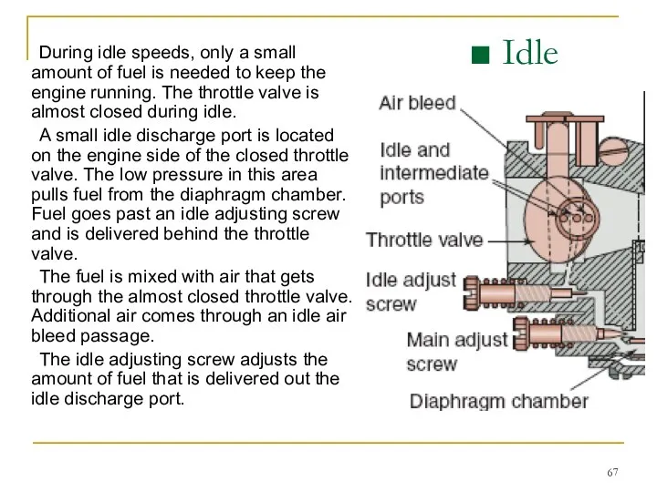
During idle speeds, only a small amount of fuel is needed
During idle speeds, only a small amount of fuel is needed
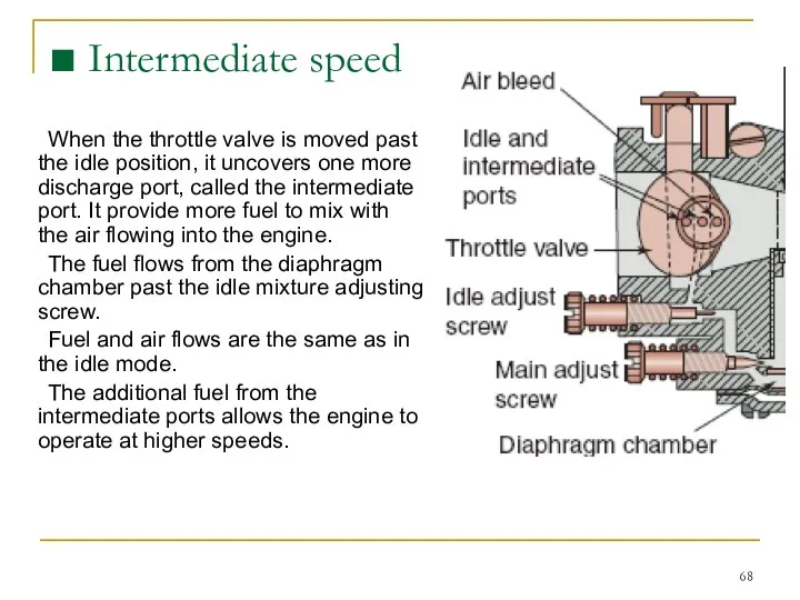
When the throttle valve is moved past the idle position, it
When the throttle valve is moved past the idle position, it
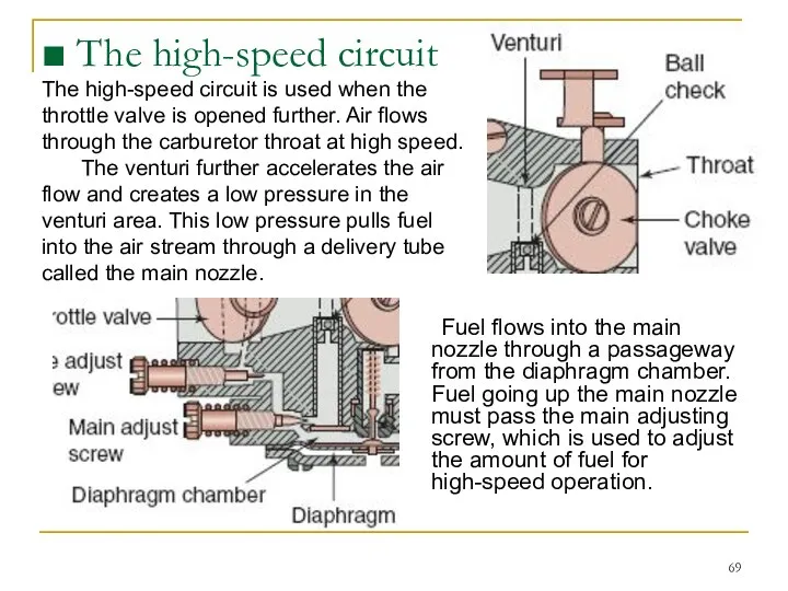
Fuel flows into the main nozzle through a passageway from the
Fuel flows into the main nozzle through a passageway from the
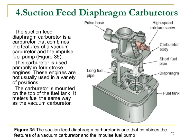
4.Suction Feed Diaphragm Carburetors
The suction feed diaphragm carburetor is a carburetor
4.Suction Feed Diaphragm Carburetors
The suction feed diaphragm carburetor is a carburetor
Some carburetors have the diaphragm mounted in a side chamber. Others
Some carburetors have the diaphragm mounted in a side chamber. Others
A diaphragm fits between the carburetor and the fuel cup. The
A diaphragm fits between the carburetor and the fuel cup. The
Fuel Systems
FUEL INJECTION
Fuel Systems
FUEL INJECTION
FUEL INJECTION
Fuel injection is the most modern method for carburetion in
FUEL INJECTION
Fuel injection is the most modern method for carburetion in

FUEL INJECTION
In today’s power equipment engines, fuel injection is becoming popular
FUEL INJECTION
In today’s power equipment engines, fuel injection is becoming popular
Conditions such as temperature, humidity, and altitude affect traditional carburetion, altering
Conditions such as temperature, humidity, and altitude affect traditional carburetion, altering
The disadvantage of fuel injection?
Cost. Due to the high cost
The disadvantage of fuel injection?
Cost. Due to the high cost
Direct Fuel Injection
The direct system injects an extremely fine mist of
Direct Fuel Injection
The direct system injects an extremely fine mist of
Indirect Fuel Injection
The indirect fuel injection system is the most common
Indirect Fuel Injection
The indirect fuel injection system is the most common
Indirect Fuel Injection
All modern fuel-injected power equipment engines use a type
Indirect Fuel Injection
All modern fuel-injected power equipment engines use a type
Fuel Injection System Сomponents
Although many small power equipment engines don’t use
Fuel Injection System Сomponents
Although many small power equipment engines don’t use
Fuel Pumps
Fuel pumps used with electronic fuel-injected power equipment engines have
Fuel Pumps
Fuel pumps used with electronic fuel-injected power equipment engines have
The fuel pump consists of an electric armature that spins between
The fuel pump consists of an electric armature that spins between
A check valve (outlet check ball) is incorporated to maintain pressure
A check valve (outlet check ball) is incorporated to maintain pressure
Fuel Filters
Before fuel enters the fuel pump, it must go through
Fuel Filters
Before fuel enters the fuel pump, it must go through
Fuel Lines
The damage in many cases will be internal and
Fuel Lines
The damage in many cases will be internal and
Fuel Pressure Regulators
The fuel pressure regulator maintains correct fuel pressure and
Fuel Pressure Regulators
The fuel pressure regulator maintains correct fuel pressure and
Fuel Injectors
The fuel injector is an electronically operated solenoid that turns
Fuel Injectors
The fuel injector is an electronically operated solenoid that turns
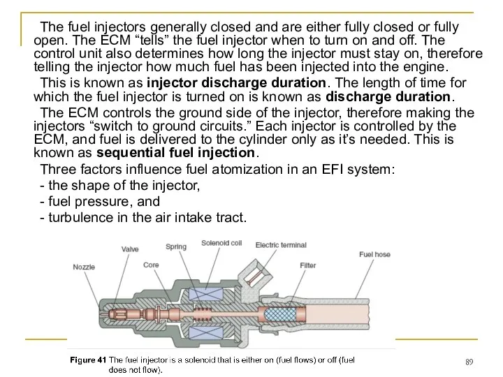
The fuel injectors generally closed and are either fully closed or
The fuel injectors generally closed and are either fully closed or
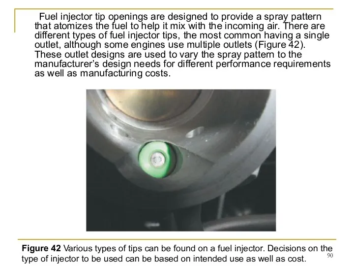
Fuel injector tip openings are designed to provide a spray pattern
Fuel injector tip openings are designed to provide a spray pattern
ECM
The heart of all fuel injection systems is the ECM. The
ECM
The heart of all fuel injection systems is the ECM. The
ECM Inputs and Outputs
The ECM has three types of inputs (Figure
ECM Inputs and Outputs
The ECM has three types of inputs (Figure
ECM Inputs and Outputs
The basic inputs provide information that the ECM
ECM Inputs and Outputs
The basic inputs provide information that the ECM
The correction inputs provide the information that the ECM needs to
The correction inputs provide the information that the ECM needs to
Various sensors monitor the engine and atmospheric conditions such as throttle
Various sensors monitor the engine and atmospheric conditions such as throttle
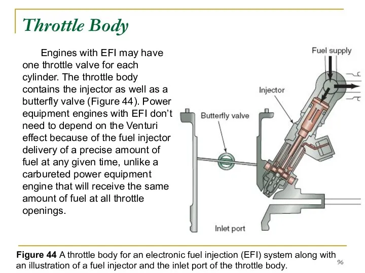
Engines with EFI may have one throttle valve for each cylinder.
Engines with EFI may have one throttle valve for each cylinder.
EFI Self-Diagnostics
Most modern power equipment engines that use EFI have a
EFI Self-Diagnostics
Most modern power equipment engines that use EFI have a
Basic Operation of the Fuel
Injection System
In a typical EFI system, the
Basic Operation of the Fuel
Injection System
In a typical EFI system, the
Electronic feedback and closed loop
Electronic feedback means the system is
Electronic feedback and closed loop
Electronic feedback means the system is
Control loops and catalytic converters
When conditions such as starting or
Control loops and catalytic converters
When conditions such as starting or
Summary
■ The primary principles of carburetor operation are atomization, the
Summary
■ The primary principles of carburetor operation are atomization, the
Wankel engine
The Wankel engine is a type of internal combustion engine
Wankel engine
The Wankel engine is a type of internal combustion engine
The engine was invented by German engineer Felix Wankel. He received
The engine was invented by German engineer Felix Wankel. He received
Design
In the Wankel engine, the four strokes of a typical Otto
Design
In the Wankel engine, the four strokes of a typical Otto
The central drive shaft 8, called the eccentric shaft or E-shaft,
The central drive shaft 8, called the eccentric shaft or E-shaft,
The best way to visualize the action of the engine is
The best way to visualize the action of the engine is
As the rotor rotates and orbitally revolves, each side of the
As the rotor rotates and orbitally revolves, each side of the
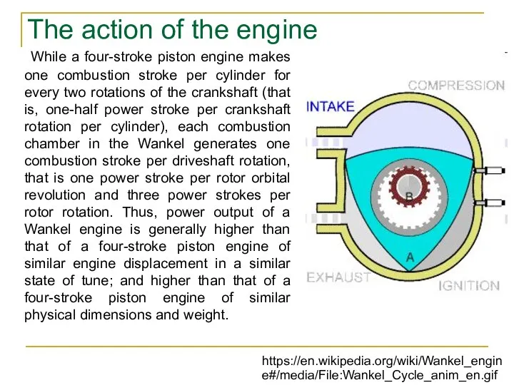
While a four-stroke piston engine makes one combustion stroke per cylinder
While a four-stroke piston engine makes one combustion stroke per cylinder
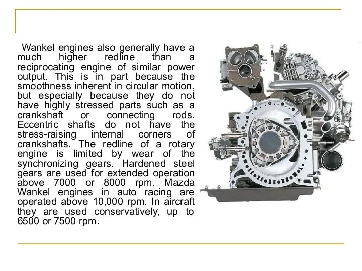
Wankel engines also generally have a much higher redline than a
Wankel engines also generally have a much higher redline than a
 Экономия электроэнергии для стиральной машины
 Оценка перспектив развития предприятия
 ПАТОФІЗІОЛОГІЯ БІЛКОВОГО ОБМІНУ
 Презентация "Санкт-Петербург-город мастеров кисти и резца" - скачать презентации по МХК
 Летний сад
  Болезни роговицы
 Сложение с учетом знака (цикл)
 Взаимодействие России со странами большой семёрки Подготовил: Майстренко Денис Группа Т-115
 КГМУ Кафедра общей хирургии Особенности обследования хирургического больного
  Либерализм. Представители
 Прикладные упражнения на уроках гимнастики
 Презентация на тему: «Биография Александра Исаевича Солженицына»
  Диагностикалау. Техникалық диагностика құрылымы
 Стратегія сталого розвитку «Україна 2020»
 Портрет в искусстве России
  СПИД – чума XXI века Презентацию подготовила Кузнецова Ольга Витальевна, учитель ГОУ ЯО Рыбинской СКОШИ I вида 2012-2013 учебный год
 Индия- «страна чудес» МХК 10 класс учитель русского языка, литературы и МХК МОУ СОШ №15 г.Благовещенска Амурской области Грязно
 Диалектика исторического процесса
 Сыбайлас жемқорлыққа байланысты құқық бұзушылық субъектiлерi
 Лекции по программированию на ассемблере
 Гарантии законности и правопорядка в современном обществе Работу подготовили студентки 2 курса ФТД гр.1309 Михайлова Анастасия и Х
 ПРОЕКТ «ДЕТСКИЙ САД»
  Женитьба по-библейски
 Весна. Основные модные тенденции
 Языки программирования высокого уровня
 Тема №9: Принятие управленческих решений
  Конструкция и техническое обслуживание пассажирских вагонов
 Аттестация персонала