- Shrink compensation

Содержание
- 2. Application Summary Material shrinkage occurs in thermoplastics as they transition from liquid state to solid state
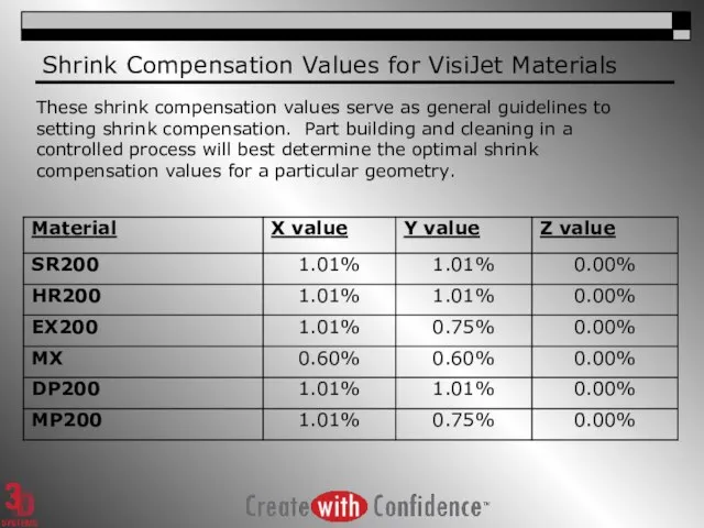
- 3. Shrink Compensation Values for VisiJet Materials These shrink compensation values serve as general guidelines to setting
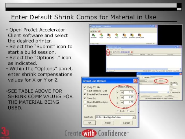
- 4. Enter Default Shrink Comps for Material in Use Open ProJet Accelerator Client software and select the
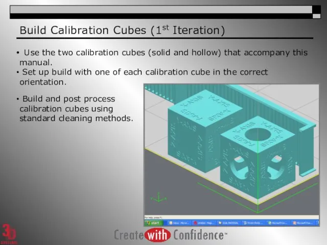
- 5. Build Calibration Cubes (1st Iteration) Use the two calibration cubes (solid and hollow) that accompany this
- 6. Take Measurements and Determine Scaling Factor Use the calculation spreadsheet that accompanies this manual to determine
- 7. Enter “Scaling Factor” for Repeat Build (2nd Iteration) Open ProJet Accelerator Client software and select the
- 8. Modify Default Shrink Comp Values Another alternative is to apply the x,y or z scaling factors
- 10. Скачать презентацию
Application Summary
Material shrinkage occurs in thermoplastics as they transition from liquid
Application Summary
Material shrinkage occurs in thermoplastics as they transition from liquid
Shrink Compensation Values for VisiJet Materials
These shrink compensation values serve as
Shrink Compensation Values for VisiJet Materials
These shrink compensation values serve as
Enter Default Shrink Comps for Material in Use
Open ProJet Accelerator
Enter Default Shrink Comps for Material in Use
Open ProJet Accelerator
Build Calibration Cubes (1st Iteration)
Use the two calibration cubes (solid
Build Calibration Cubes (1st Iteration)
Use the two calibration cubes (solid
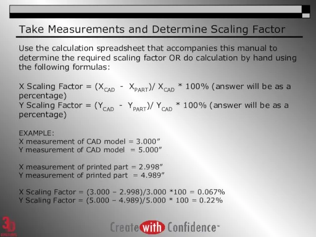
Take Measurements and Determine Scaling Factor
Use the calculation spreadsheet that accompanies
Take Measurements and Determine Scaling Factor
Use the calculation spreadsheet that accompanies
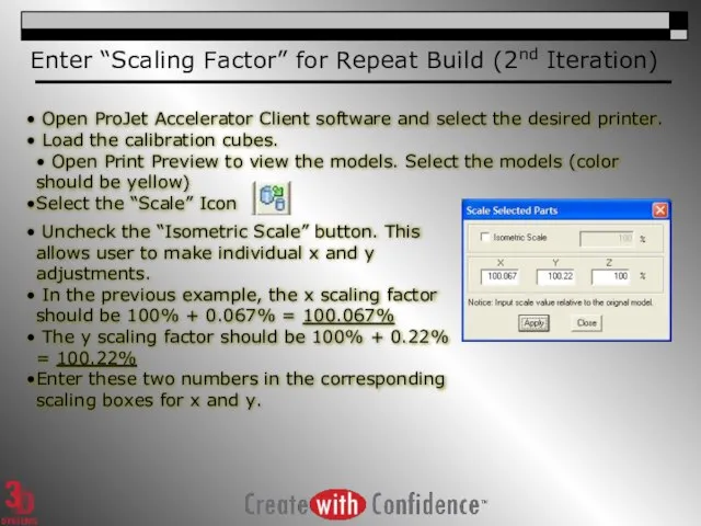
Enter “Scaling Factor” for Repeat Build (2nd Iteration)
Open ProJet Accelerator
Enter “Scaling Factor” for Repeat Build (2nd Iteration)
Open ProJet Accelerator
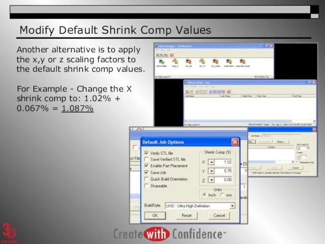
Modify Default Shrink Comp Values
Another alternative is to apply the
Modify Default Shrink Comp Values
Another alternative is to apply the
 Программное обеспечение компьютера
 Композиция. Правила и приемы
 Желілік операциялық жүйелер
 Схема маршрута метро
 Сервис онлайн голосования собственников МКД №С1-53417
 Проектирование и реализация сети, настройка на маршрутизаторе службы DHCP в программе Cisco Packet Tracer
 Средства информационных и коммуникационных технологий. Логические функции и схемы – основа элементной базы компьютера
 ЭВМ и периферийные устройства. Память вычислительных машин. (Лекция 4)
 Виды и характеристики памяти. Дисциплина Структура компьютерных средств. Тема №4. Занятие №1/1
 3 класс
  Нормальные формы баз данных
 Алгоритмы и способы их описания
 Основні поняття комп'ютерної графіки
 Подсистема оптических приводов
 Анализ бизнес информации – основные принципы
 Характеристика электронных картографических систем
 Приветствую Вас на курсе Java!
 Разбор заданий первой части. Информатика. ОГЭ-2016
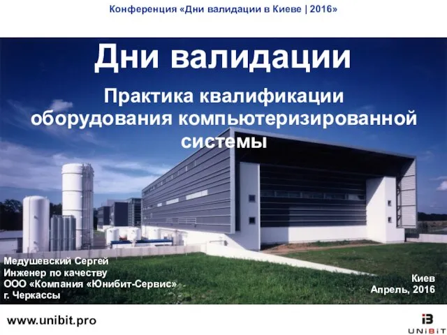 Дни валидации. Практика квалификации оборудования компьютеризированной системы
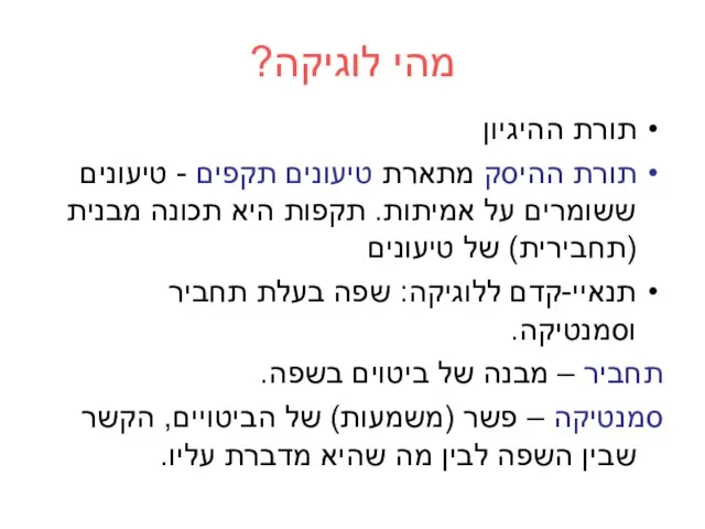 מהי לוגיקה
 Презентация "Руководство пользователя программы "Microsoft Word"" - скачать презентации по Информатике
 Презентация "Информационный калейдоскоп" - скачать презентации по Информатике
 Файлдық жүйелер мен ДҚБЖ арасындағы негізгі айырмашылық
 Модернизация ИТ-инфраструктуры с помощью Windows Server 2016 (совместно с Veeam Software)
 Программирование сервера баз данных
 Что такое языки программирования и как их можно применить
 Алгоритмы, структуры алгоритмов, структурное программирование
 Киберпреступность и кибертерроризм определение понятия «киберпреступность»; определение понятия «кибертерроризм»; способы, с