- Aircraft type course: airbus a320 category b1

Содержание
- 2. ATA 27 FLIGHT CONTROLS GENERAL Flight Controls System Component Location.................................................... Side Stick Description/Operation...................................................................... Flight Control Laws...........................................................................................
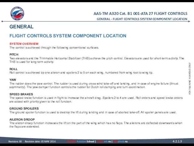
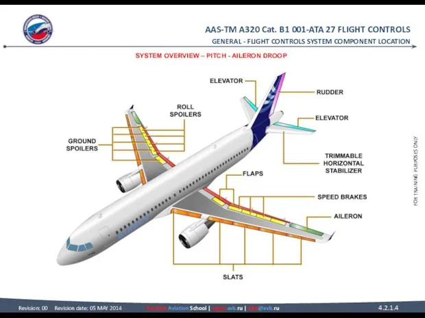
- 3. GENERAL FLIGHT CONTROLS SYSTEM COMPONENT LOCATION SYSTEM OVERVIEW The control is achieved through the following conventional
- 4. GENERAL - FLIGHT CONTROLS SYSTEM COMPONENT LOCATION SYSTEM OVERVIEW – PITCH - AILERON DROOP
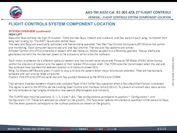
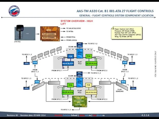
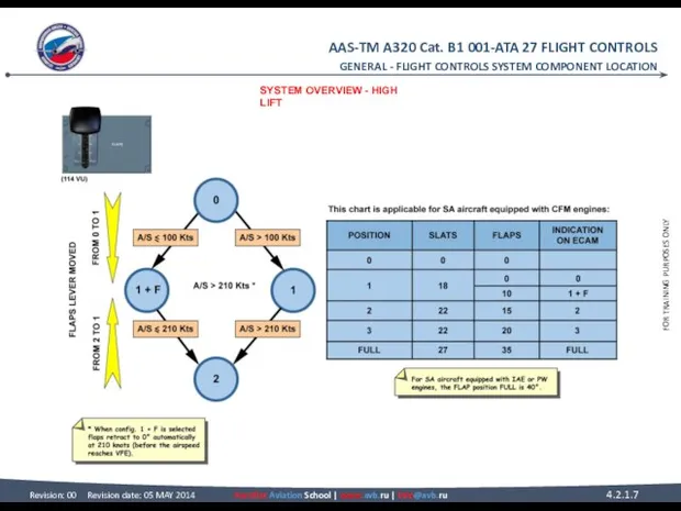
- 5. FLIGHT CONTROLS SYSTEM COMPONENT LOCATION SYSTEM OVERVIEW (continued) HIGH LIFT Slats and flaps achieve the high
- 6. GENERAL - FLIGHT CONTROLS SYSTEM COMPONENT LOCATION SYSTEM OVERVIEW - HIGH LIFT
- 7. GENERAL - FLIGHT CONTROLS SYSTEM COMPONENT LOCATION SYSTEM OVERVIEW - HIGH LIFT
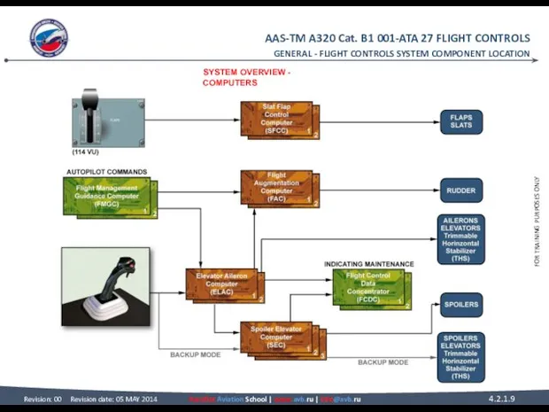
- 8. FLIGHT CONTROLS SYSTEM COMPONENT LOCATION SYSTEM OVERVIEW (continued) COMPUTERS A computer arrangement permanently controls and monitors
- 9. GENERAL - FLIGHT CONTROLS SYSTEM COMPONENT LOCATION SYSTEM OVERVIEW - COMPUTERS
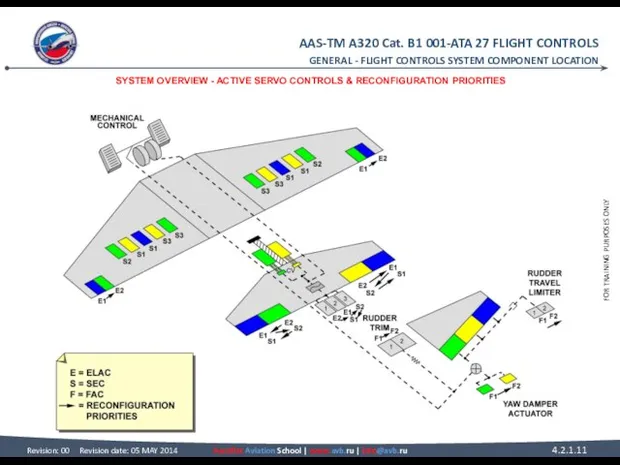
- 10. FLIGHT CONTROLS SYSTEM COMPONENT LOCATION SYSTEM OVERVIEW (continued) ACTIVE SERVO CONTROLS There are two servo controls
- 11. GENERAL - FLIGHT CONTROLS SYSTEM COMPONENT LOCATION SYSTEM OVERVIEW - ACTIVE SERVO CONTROLS & RECONFIGURATION PRIORITIES
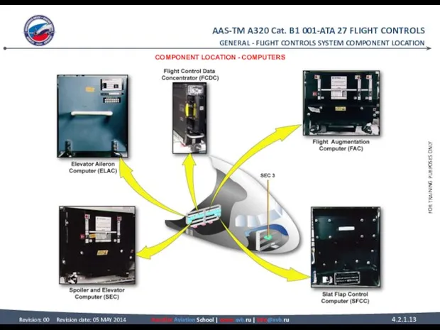
- 12. FLIGHT CONTROLS SYSTEM COMPONENT LOCATION COMPONENT LOCATION COMPUTERS All the flight control computers are located in
- 13. GENERAL - FLIGHT CONTROLS SYSTEM COMPONENT LOCATION COMPONENT LOCATION - COMPUTERS
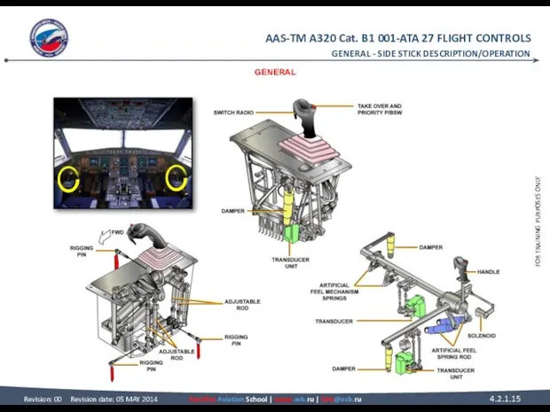
- 14. SIDE STICK DESCRIPTION/OPERATION GENERAL The main function of the side sticks is to transmit to the
- 15. GENERAL - SIDE STICK DESCRIPTION/OPERATION GENERAL
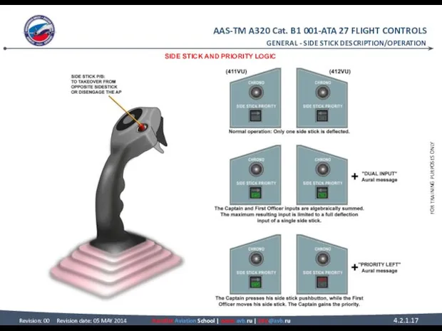
- 16. SIDE STICK DESCRIPTION/OPERATION SIDE STICK AND PRIORITY LOGIC Side sticks, one on each lateral console, are
- 17. GENERAL - SIDE STICK DESCRIPTION/OPERATION SIDE STICK AND PRIORITY LOGIC
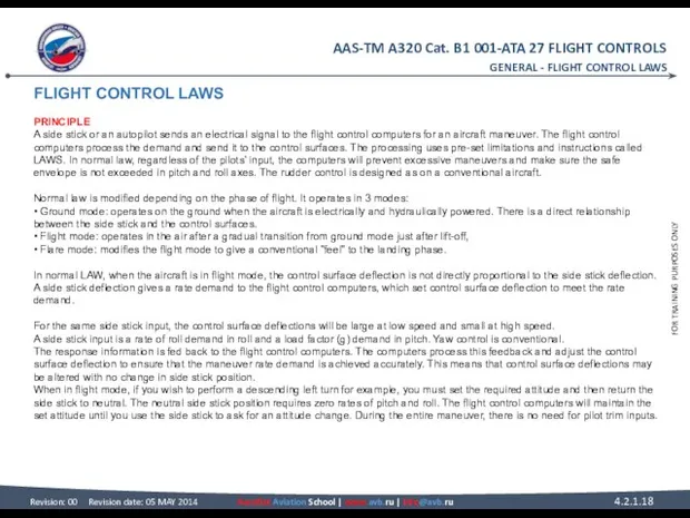
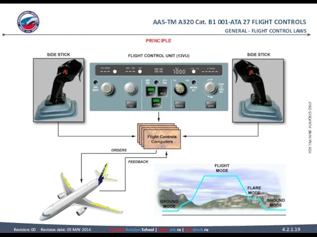
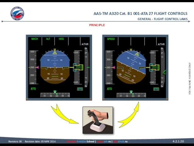
- 18. FLIGHT CONTROL LAWS PRINCIPLE A side stick or an autopilot sends an electrical signal to the
- 19. GENERAL - FLIGHT CONTROL LAWS PRINCIPLE
- 20. GENERAL - FLIGHT CONTROL LAWS PRINCIPLE
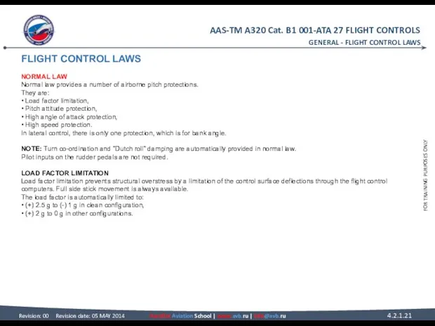
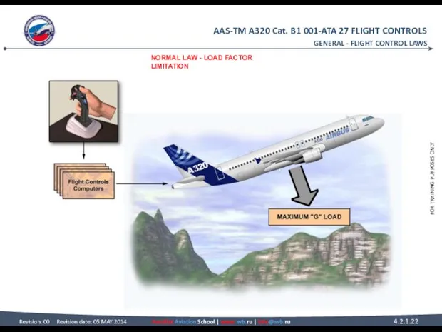
- 21. FLIGHT CONTROL LAWS NORMAL LAW Normal law provides a number of airborne pitch protections. They are:
- 22. GENERAL - FLIGHT CONTROL LAWS NORMAL LAW - LOAD FACTOR LIMITATION
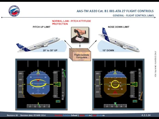
- 23. FLIGHT CONTROL LAWS NORMAL LAW (continued) PITCH ATTITUDE PROTECTION If the aircraft reaches the pitch attitude
- 24. GENERAL - FLIGHT CONTROL LAWS NORMAL LAW - PITCH ATTITUDE PROTECTION
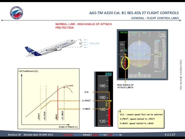
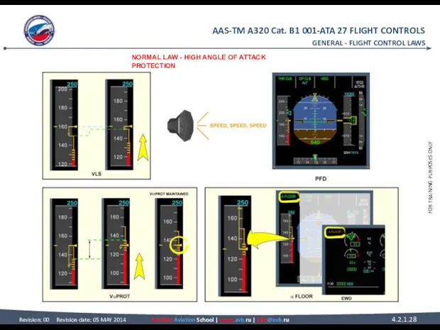
- 25. FLIGHT CONTROL LAWS NORMAL LAW (continued) HIGH ANGLE OF ATTACK PROTECTION The high Angle Of Attack
- 26. NORMAL LAW (continued) HIGH ANGLE OF ATTACK PROTECTION (continued) With autothrust inoperative or not engaged, the
- 27. GENERAL - FLIGHT CONTROL LAWS NORMAL LAW - HIGH ANGLE OF ATTACK PROTECTION
- 28. GENERAL - FLIGHT CONTROL LAWS NORMAL LAW - HIGH ANGLE OF ATTACK PROTECTION
- 29. GENERAL - FLIGHT CONTROL LAWS NORMAL LAW - HIGH ANGLE OF ATTACK PROTECTION
- 30. FLIGHT CONTROL LAWS NORMAL LAW (continued) HIGH SPEED PROTECTION The high speed protection is designed to
- 31. GENERAL - FLIGHT CONTROL LAWS NORMAL LAW - HIGH SPEED PROTECTION
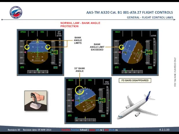
- 32. FLIGHT CONTROL LAWS NORMAL LAW (continued) BANK ANGLE PROTECTION Under normal law, bank angle protection limits
- 33. GENERAL - FLIGHT CONTROL LAWS NORMAL LAW - BANK ANGLE PROTECTION
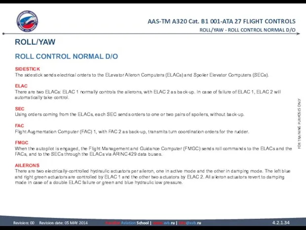
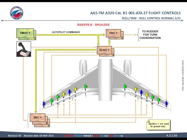
- 34. ROLL/YAW ROLL CONTROL NORMAL D/O SIDESTICK The sidestick sends electrical orders to the ELevator Aileron Computers
- 35. SPOILERS Each spoiler is powered by one hydraulic actuator. Surfaces are automatically retracted if a fault
- 36. ROLL/YAW - ROLL CONTROL NORMAL D/O SIDESTICK - SPOILERS
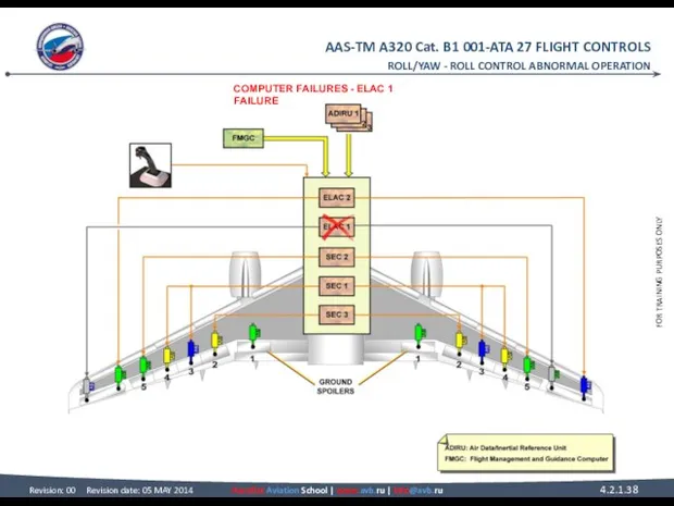
- 37. ROLL CONTROL ABNORMAL OPERATION COMPUTER FAILURES A computer failure can engage a lateral abnormal configuration. ELAC
- 38. ROLL/YAW - ROLL CONTROL ABNORMAL OPERATION COMPUTER FAILURES - ELAC 1 FAILURE
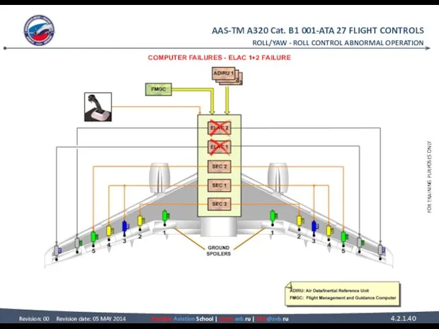
- 39. ROLL CONTROL ABNORMAL OPERATION COMPUTER FAILURES (continued) ELAC 1+2 FAILURE In case of loss of both
- 40. ROLL/YAW - ROLL CONTROL ABNORMAL OPERATION COMPUTER FAILURES - ELAC 1+2 FAILURE
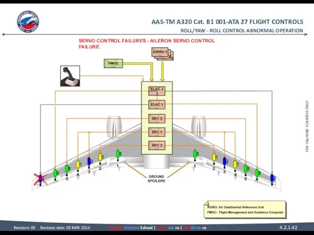
- 41. ROLL CONTROL ABNORMAL OPERATION SERVO CONTROL FAILURES AILERON SERVO CONTROL FAILURE In case of failure of
- 42. ROLL/YAW - ROLL CONTROL ABNORMAL OPERATION SERVO CONTROL FAILURES - AILERON SERVO CONTROL FAILURE
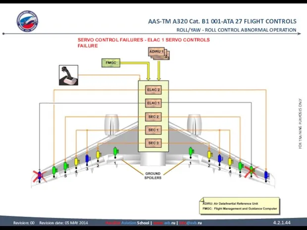
- 43. ROLL CONTROL ABNORMAL OPERATION SERVO CONTROL FAILURES (continued) ELAC 1 SERVO CONTROLS FAILURE In case of
- 44. ROLL/YAW - ROLL CONTROL ABNORMAL OPERATION SERVO CONTROL FAILURES - ELAC 1 SERVO CONTROLS FAILURE
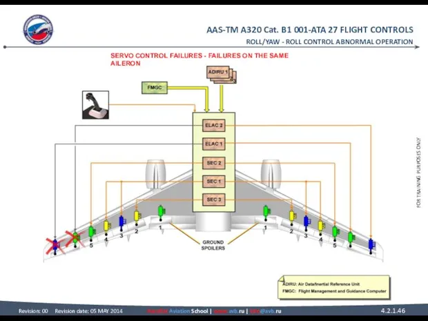
- 45. ROLL CONTROL ABNORMAL OPERATION SERVO CONTROL FAILURES (continued) FAILURES ON THE SAME AILERON In case of
- 46. ROLL/YAW - ROLL CONTROL ABNORMAL OPERATION SERVO CONTROL FAILURES - FAILURES ON THE SAME AILERON
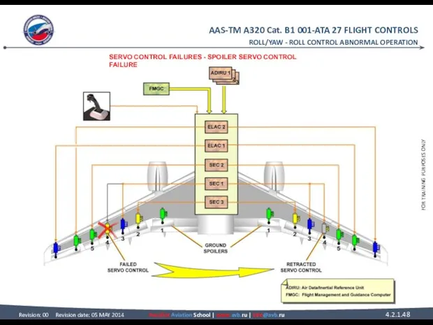
- 47. ROLL CONTROL ABNORMAL OPERATION SERVO CONTROL FAILURES (continued) SPOILER SERVO CONTROL FAILURE In case of failure
- 48. ROLL/YAW - ROLL CONTROL ABNORMAL OPERATION SERVO CONTROL FAILURES - SPOILER SERVO CONTROL FAILURE
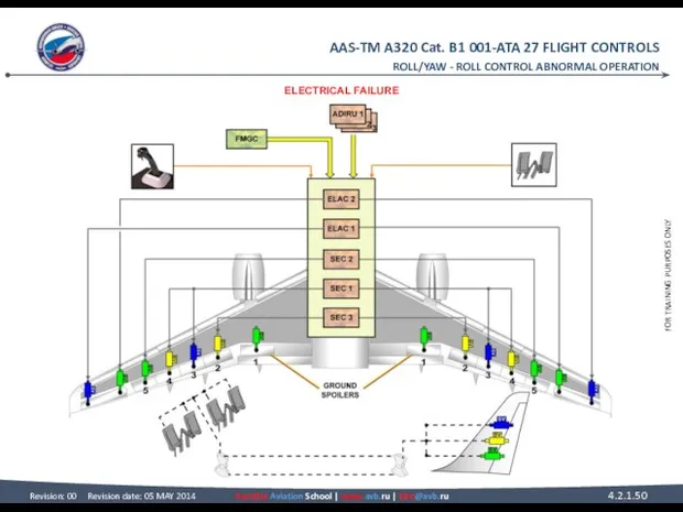
- 49. ROLL CONTROL ABNORMAL OPERATION ELECTRICAL FAILURE In case of total electrical loss, induced roll is obtained
- 50. ROLL/YAW - ROLL CONTROL ABNORMAL OPERATION ELECTRICAL FAILURE
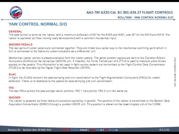
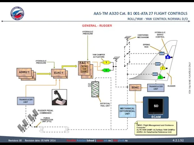
- 51. YAW CONTROL NORMAL D/O GENERAL The yaw control is done by the rudder, with a maximum
- 52. ROLL/YAW - YAW CONTROL NORMAL D/O GENERAL - RUDDER
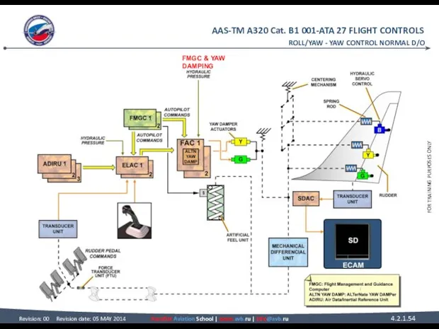
- 53. YAW CONTROL NORMAL D/O FMGC When the autopilot is engaged, the Flight Management and Guidance Computers
- 54. ROLL/YAW - YAW CONTROL NORMAL D/O FMGC & YAW DAMPING
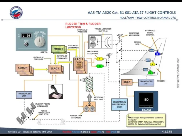
- 55. YAW CONTROL NORMAL D/O RUDDER TRIM The rudder trim is achieved by one or two electric
- 56. ROLL/YAW - YAW CONTROL NORMAL D/O RUDDER TRIM & RUDDER LIMITATION
- 57. YAW CONTROL ABNORMAL D/O ALTERNATE LAW The alternate yaw damper law computed in the Flight Augmentation
- 58. ALTERNATE LAW & YAW MECHANICAL ROLL/YAW - YAW CONTROL ABNORMAL D/O
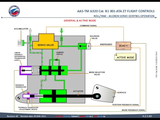
- 59. AILERON SERVO CONTROL OPERATION GENERAL Each aileron is equipped with two identical electro-hydraulic servo-controls. These servo-controls
- 60. ROLL/YAW - AILERON SERVO CONTROL OPERATION GENERAL & ACTIVE MODE
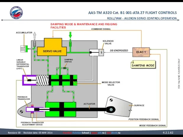
- 61. AILERON SERVO CONTROL OPERATION DAMPING MODE In damping mode, the actuator follows the control surface movements.
- 62. ROLL/YAW - AILERON SERVO CONTROL OPERATION DAMPING MODE & MAINTENANCE AND RIGGING FACILITIES
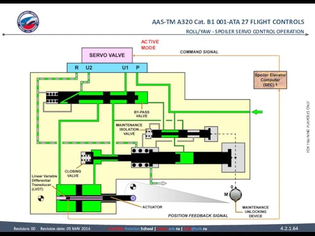
- 63. SPOILER SERVO CONTROL OPERATION ACTIVE MODE In active mode the spoiler servo control actuator is hydraulically
- 64. ROLL/YAW - SPOILER SERVO CONTROL OPERATION ACTIVE MODE
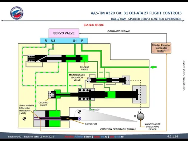
- 65. SPOILER SERVO CONTROL OPERATION BIASED MODE The servo-control actuator is pressurized. Due to an electrical failure
- 66. ROLL/YAW - SPOILER SERVO CONTROL OPERATION BIASED MODE
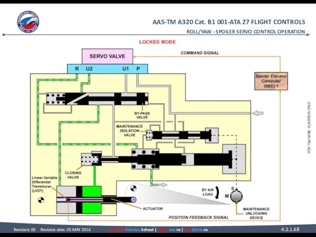
- 67. SPOILER SERVO CONTROL OPERATION LOCKED MODE In locked mode, the hydraulic pressure is lost. The closing
- 68. ROLL/YAW - SPOILER SERVO CONTROL OPERATION LOCKED MODE
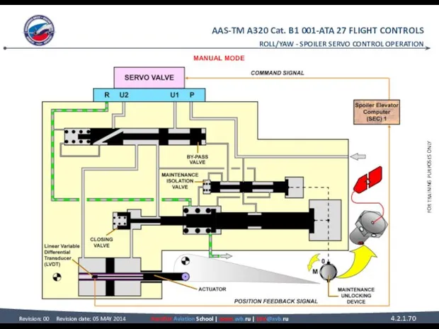
- 69. SPOILER SERVO CONTROL OPERATION MANUAL MODE To be unlocked, the servo control actuator must be depressurized.
- 70. ROLL/YAW - SPOILER SERVO CONTROL OPERATION MANUAL MODE
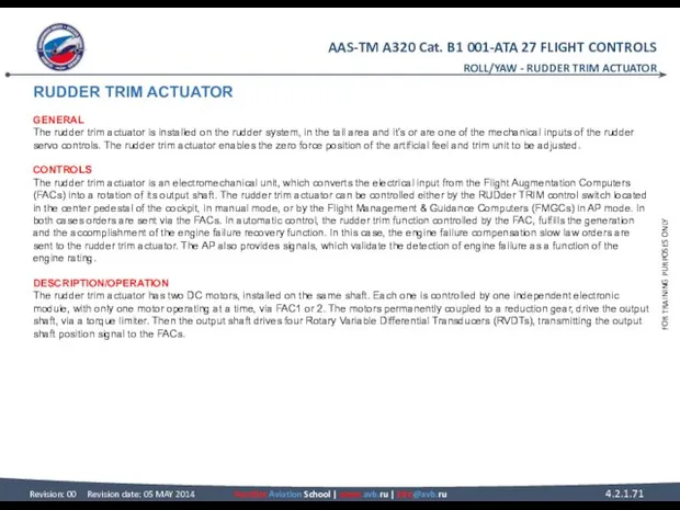
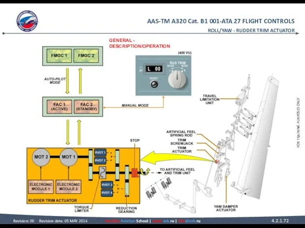
- 71. RUDDER TRIM ACTUATOR GENERAL The rudder trim actuator is installed on the rudder system, in the
- 72. ROLL/YAW - RUDDER TRIM ACTUATOR GENERAL - DESCRIPTION/OPERATION
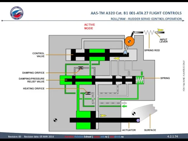
- 73. RUDDER SERVO CONTROL OPERATION ACTIVE MODE When the rudder servo control actuator is in active mode,
- 74. ACTIVE MODE ROLL/YAW - RUDDER SERVO CONTROL OPERATION
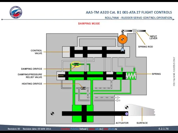
- 75. RUDDER SERVO CONTROL OPERATION DAMPING MODE The rudder servo control actuator changes to damping mode, as
- 76. DAMPING MODE ROLL/YAW - RUDDER SERVO CONTROL OPERATION
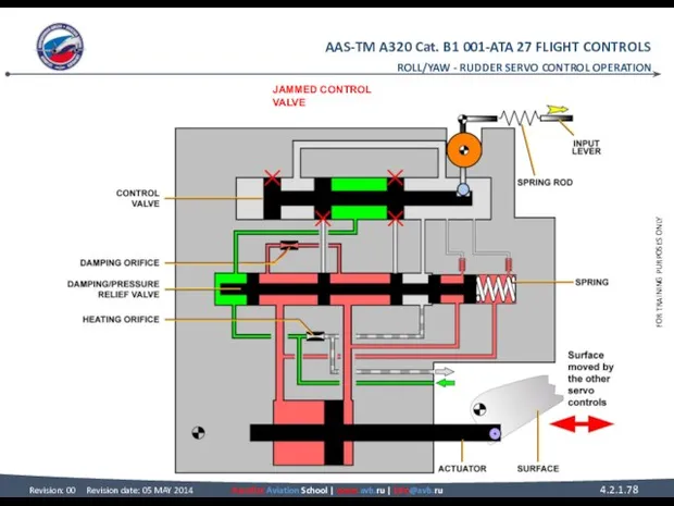
- 77. RUDDER SERVO CONTROL OPERATION JAMMED CONTROL VALVE If the control valve jams, the rudder servo control
- 78. ROLL/YAW - RUDDER SERVO CONTROL OPERATION JAMMED CONTROL VALVE
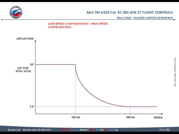
- 79. RUDDER LIMITER OPERATION LOW SPEED CONFIGURATION Under 160 kts the stops are in low-speed configuration. Full
- 80. ROLL/YAW - RUDDER LIMITER OPERATION LOW SPEED CONFIGURATION - HIGH SPEED CONFIGURATION
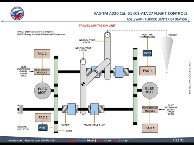
- 81. RUDDER LIMITER OPERATION TRAVEL LIMITATION UNIT The mechanical design of the Travel Limitation Unit (TLU) is
- 82. ROLL/YAW - RUDDER LIMITER OPERATION TRAVEL LIMITATION UNIT
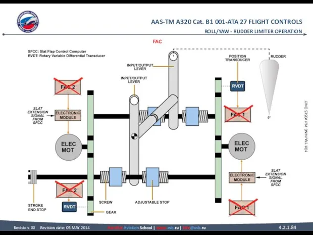
- 83. RUDDER LIMITER OPERATION FAC If both FACs fail, the rudder travel limitation value is frozen immediately.
- 84. ROLL/YAW - RUDDER LIMITER OPERATION FAC
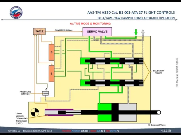
- 85. YAW DAMPER SERVO ACTUATOR OPERATION ACTIVE MODE The actuator is in active mode when both solenoid
- 86. ROLL/YAW - YAW DAMPER SERVO ACTUATOR OPERATION ACTIVE MODE & MONITORING
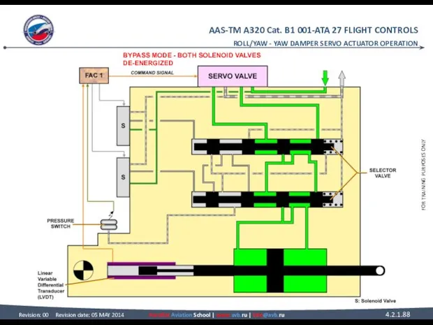
- 87. YAW DAMPER SERVO ACTUATOR OPERATION BYPASS MODE BOTH SOLENOID VALVES DE-ENERGIZED The two-solenoid valves are de-energized
- 88. ROLL/YAW - YAW DAMPER SERVO ACTUATOR OPERATION BYPASS MODE - BOTH SOLENOID VALVES DE-ENERGIZED
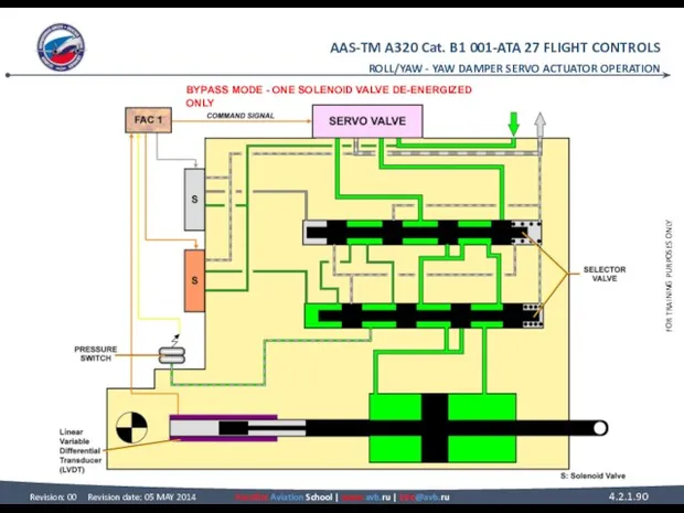
- 89. YAW DAMPER SERVO ACTUATOR OPERATION BYPASS MODE (continued) ONE SOLENOID VALVE DE-ENERGIZED ONLY In case of
- 90. ROLL/YAW - YAW DAMPER SERVO ACTUATOR OPERATION BYPASS MODE - ONE SOLENOID VALVE DE-ENERGIZED ONLY
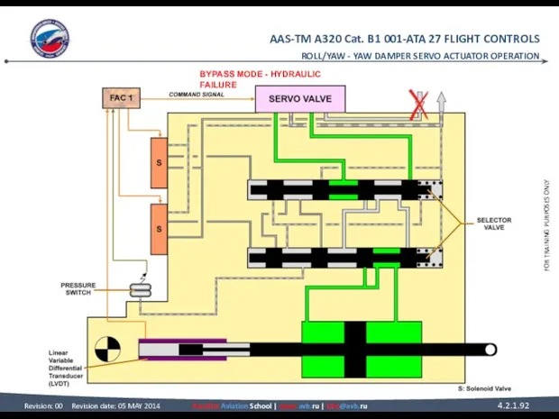
- 91. YAW DAMPER SERVO ACTUATOR OPERATION BYPASS MODE (continued) HYDRAULIC FAILURE With no hydraulic pressure, the two
- 92. ROLL/YAW - YAW DAMPER SERVO ACTUATOR OPERATION BYPASS MODE - HYDRAULIC FAILURE
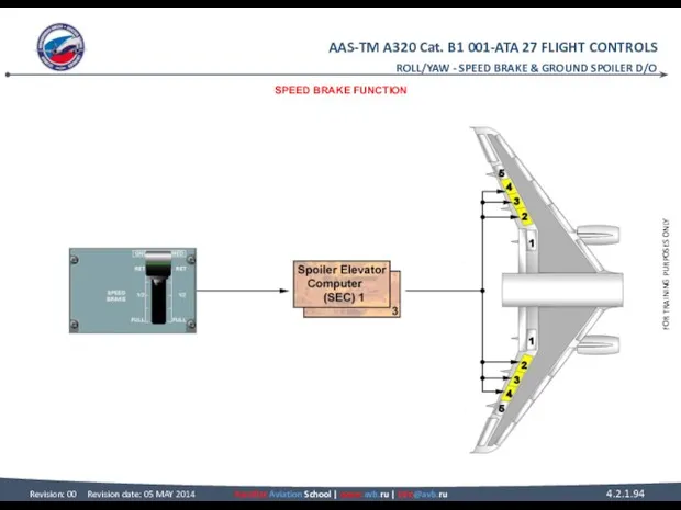
- 93. SPEED BRAKE & GROUND SPOILER D/O SPEED BRAKE FUNCTION The speed brake function is commanded in
- 94. ROLL/YAW - SPEED BRAKE & GROUND SPOILER D/O SPEED BRAKE FUNCTION
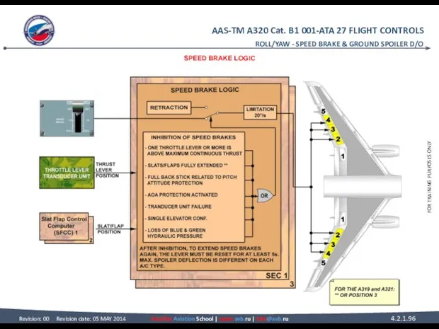
- 95. SPEED BRAKE & GROUND SPOILER D/O SPEED BRAKE LOGIC The speed brake control lever sends commands
- 96. ROLL/YAW - SPEED BRAKE & GROUND SPOILER D/O SPEED BRAKE LOGIC
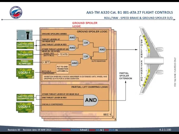
- 97. ROLL/YAW - SPEED BRAKE & GROUND SPOILER D/O SPEED BRAKE & GROUND SPOILER D/O GROUND SPOILER
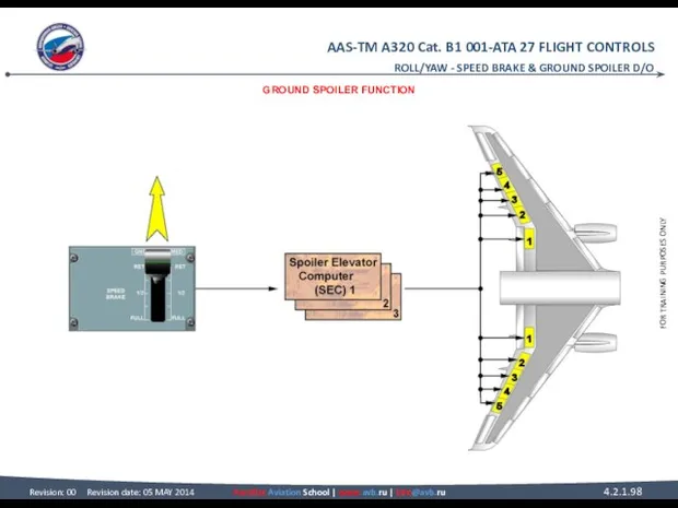
- 98. ROLL/YAW - SPEED BRAKE & GROUND SPOILER D/O GROUND SPOILER FUNCTION
- 99. ROLL/YAW - SPEED BRAKE & GROUND SPOILER D/O SPEED BRAKE & GROUND SPOILER D/O GROUND SPOILER
- 100. ROLL/YAW - SPEED BRAKE & GROUND SPOILER D/O GROUND SPOILER LOGIC
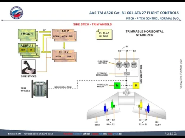
- 101. PITCH - PITCH CONTROL NORMAL D/O PITCH PITCH CONTROL NORMAL D/O SIDE STICK The side stick
- 102. SIDE STICK - TRIM WHEELS PITCH - PITCH CONTROL NORMAL D/O
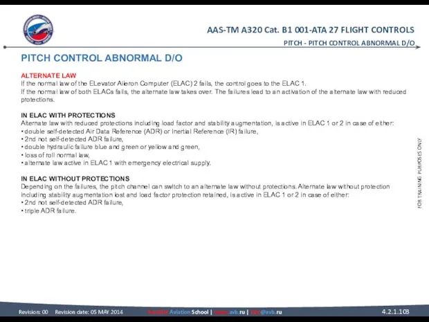
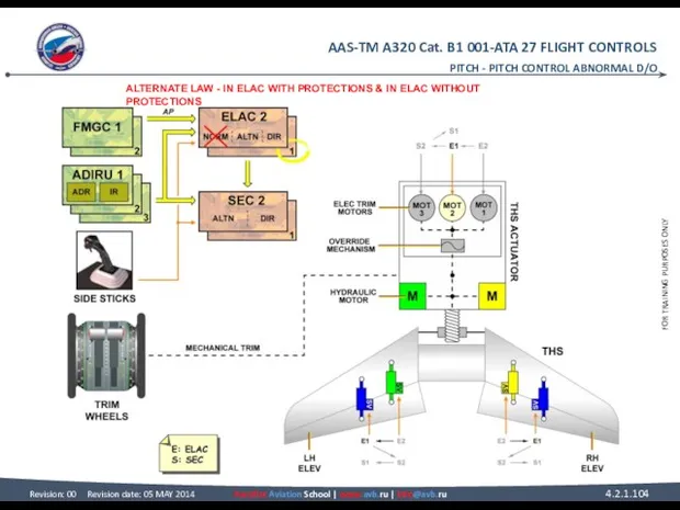
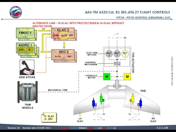
- 103. PITCH CONTROL ABNORMAL D/O ALTERNATE LAW If the normal law of the ELevator Aileron Computer (ELAC)
- 104. PITCH - PITCH CONTROL ABNORMAL D/O ALTERNATE LAW - IN ELAC WITH PROTECTIONS & IN ELAC
- 105. PITCH - PITCH CONTROL ABNORMAL D/O ALTERNATE LAW - IN ELAC WITH PROTECTIONS & IN ELAC
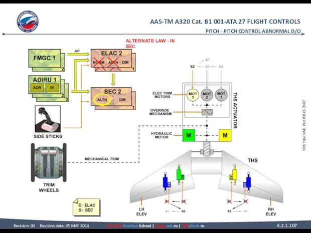
- 106. PITCH CONTROL ABNORMAL D/O ALTERNATE LAW (continued) IN SEC After a double ELAC failure, alternate law
- 107. PITCH - PITCH CONTROL ABNORMAL D/O ALTERNATE LAW - IN SEC
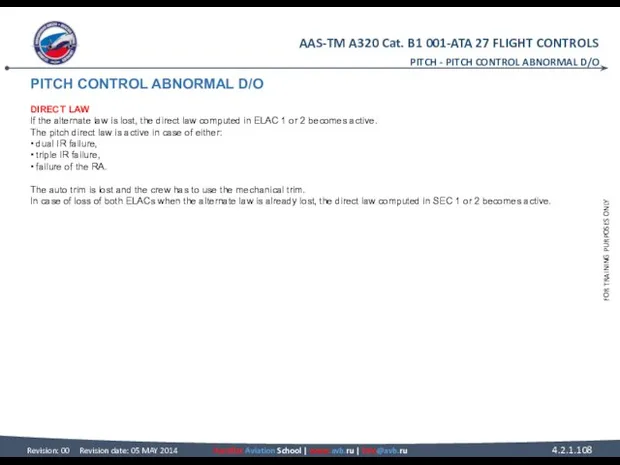
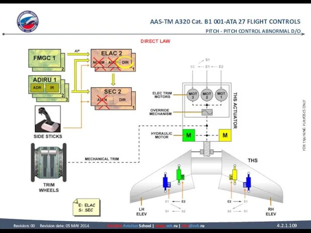
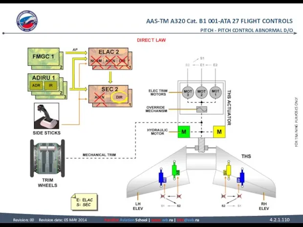
- 108. PITCH CONTROL ABNORMAL D/O DIRECT LAW If the alternate law is lost, the direct law computed
- 109. PITCH - PITCH CONTROL ABNORMAL D/O DIRECT LAW
- 110. PITCH - PITCH CONTROL ABNORMAL D/O DIRECT LAW
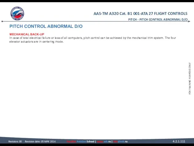
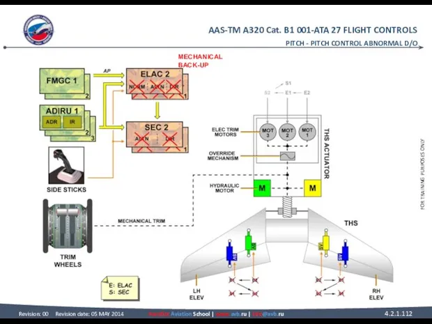
- 111. PITCH CONTROL ABNORMAL D/O MECHANICAL BACK-UP In case of total electrical failure or loss of all
- 112. PITCH - PITCH CONTROL ABNORMAL D/O MECHANICAL BACK-UP
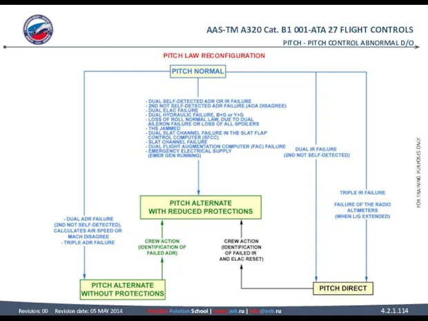
- 113. PITCH CONTROL ABNORMAL D/O PITCH LAW RECONFIGURATION This diagram summarizes the pitch law reconfiguration. PITCH -
- 114. PITCH - PITCH CONTROL ABNORMAL D/O PITCH LAW RECONFIGURATION
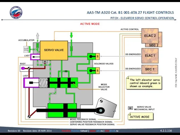
- 115. ELEVATOR SERVO CONTROL OPERATION ACTIVE MODE When the elevator servo control is in the active mode,
- 116. PITCH - ELEVATOR SERVO CONTROL OPERATION ACTIVE MODE
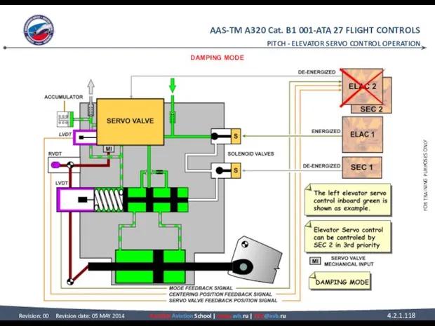
- 117. ELEVATOR SERVO CONTROL OPERATION DAMPING MODE In case of a computer failure (e.g. ELAC2 failure), the
- 118. PITCH - ELEVATOR SERVO CONTROL OPERATION DAMPING MODE
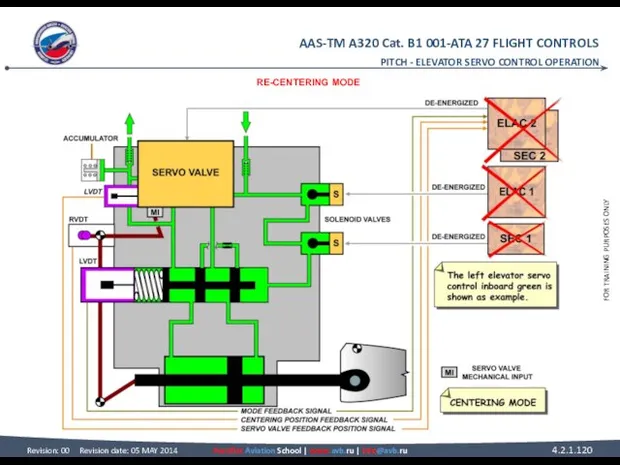
- 119. ELEVATOR SERVO CONTROL OPERATION RE-CENTERING MODE When the elevator servo control is in the re-centering mode,
- 120. PITCH - ELEVATOR SERVO CONTROL OPERATION RE-CENTERING MODE
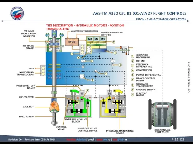
- 121. THS ACTUATOR OPERATION THS DESCRIPTION HYDRAULIC MOTORS Both hydraulic motors drive the ball screw actuator through
- 122. PITCH - THS ACTUATOR OPERATION THS DESCRIPTION - HYDRAULIC MOTORS - POSITION TRANSDUCERS
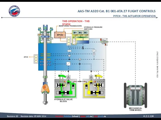
- 123. THS ACTUATOR OPERATION THS OPERATION THS STATIC In the Static mode: • there is no input
- 124. PITCH - THS ACTUATOR OPERATION THS OPERATION - THS STATIC
- 125. THS ACTUATOR OPERATION THS OPERATION (continued) NORMAL OPERATION ELAC2 (in normal control) sends a drive command
- 126. PITCH - THS ACTUATOR OPERATION THS OPERATION - NORMAL OPERATION
- 127. PITCH - THS ACTUATOR OPERATION THS OPERATION - NORMAL OPERATION
- 128. PITCH - THS ACTUATOR OPERATION THS OPERATION - NORMAL OPERATION
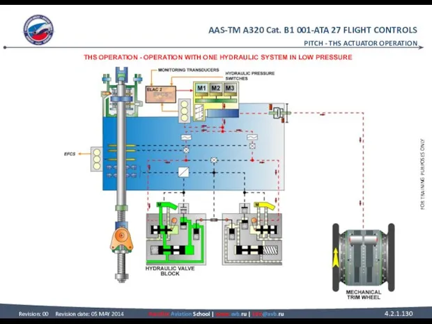
- 129. THS ACTUATOR OPERATION THS OPERATION (continued) OPERATION WITH ONE HYDRAULIC SYSTEM IN LOW PRESSURE Since the
- 130. PITCH - THS ACTUATOR OPERATION THS OPERATION - OPERATION WITH ONE HYDRAULIC SYSTEM IN LOW PRESSURE
- 131. PITCH - THS ACTUATOR OPERATION THS OPERATION - OPERATION WITH ONE HYDRAULIC SYSTEM IN LOW PRESSURE
- 132. PITCH - THS ACTUATOR OPERATION THS OPERATION - OPERATION WITH ONE HYDRAULIC SYSTEM IN LOW PRESSURE
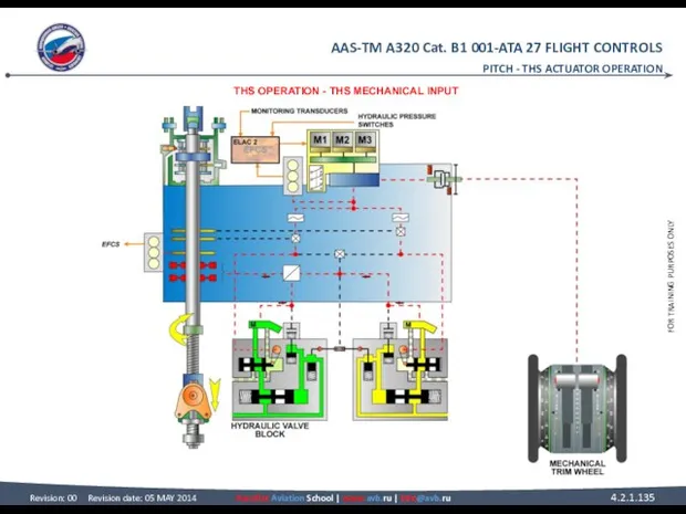
- 133. THS ACTUATOR OPERATION THS OPERATION (continued) THS MECHANICAL INPUT A mechanical input link is connected to
- 134. PITCH - THS ACTUATOR OPERATION THS OPERATION - THS MECHANICAL INPUT
- 135. PITCH - THS ACTUATOR OPERATION THS OPERATION - THS MECHANICAL INPUT
- 136. PITCH - THS ACTUATOR OPERATION THS OPERATION - THS MECHANICAL INPUT
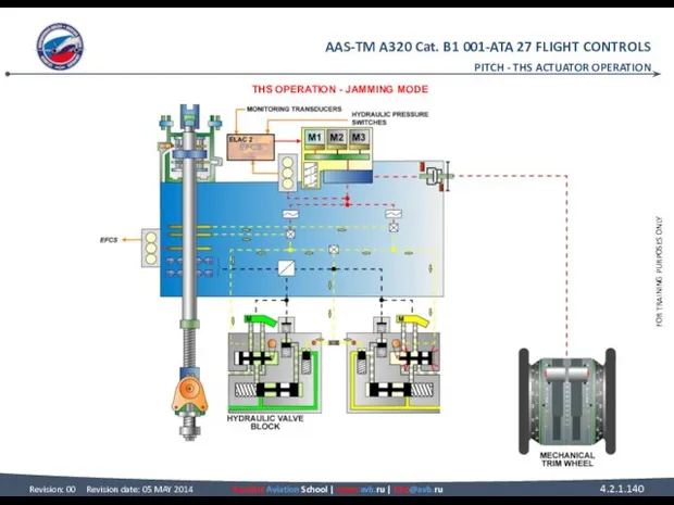
- 137. THS ACTUATOR OPERATION THS OPERATION (continued) JAMMING MODE ELAC2 (in normal control) sends a drive command
- 138. PITCH - THS ACTUATOR OPERATION THS OPERATION - JAMMING MODE
- 139. PITCH - THS ACTUATOR OPERATION THS OPERATION - JAMMING MODE
- 140. PITCH - THS ACTUATOR OPERATION THS OPERATION - JAMMING MODE
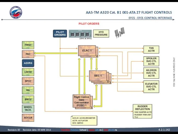
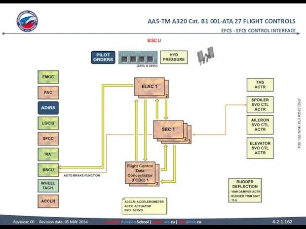
- 141. EFCS EFCS CONTROL INTERFACE PILOT ORDERS The pilot orders like side stick, speed brake, ground spoiler
- 142. EFCS - EFCS CONTROL INTERFACE PILOT ORDERS
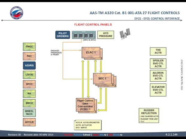
- 143. EFCS CONTROL INTERFACE FLIGHT CONTROL PANELS P/Bs located on the FLighT ConTroL panels are used to
- 144. EFCS - EFCS CONTROL INTERFACE FLIGHT CONTROL PANELS
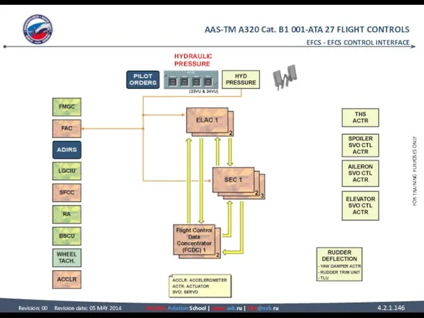
- 145. EFCS CONTROL INTERFACE HYDRAULIC PRESSURE The hydraulic pressure status is sent to the ELACs and SECs
- 146. EFCS - EFCS CONTROL INTERFACE HYDRAULIC PRESSURE
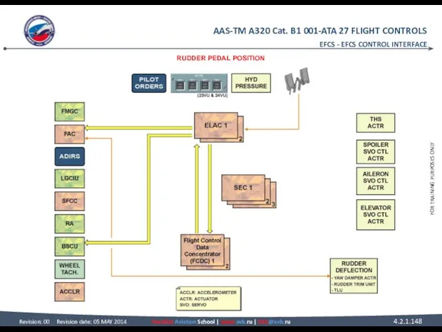
- 147. EFCS CONTROL INTERFACE RUDDER PEDAL POSITION The signal from the rudder pedal transducers is used for
- 148. EFCS - EFCS CONTROL INTERFACE RUDDER PEDAL POSITION
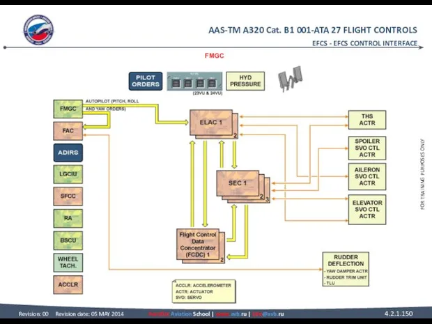
- 149. EFCS CONTROL INTERFACE FMGC If the autopilot is active, pitch, roll and yaw orders computed by
- 150. EFCS - EFCS CONTROL INTERFACE FMGC
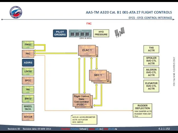
- 151. EFCS CONTROL INTERFACE FAC The FACs receive rudder deflection information computed either by the ELACs or
- 152. EFCS - EFCS CONTROL INTERFACE FAC
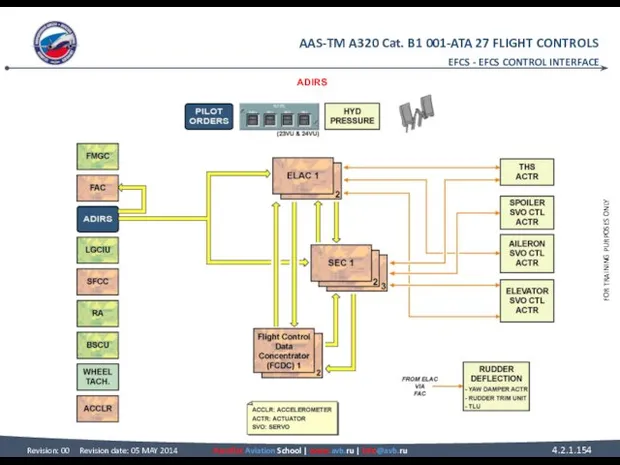
- 153. EFCS CONTROL INTERFACE ADIRS The Air Data/Inertial Reference System (ADIRS) transmits air data and inertial reference
- 154. EFCS - EFCS CONTROL INTERFACE ADIRS
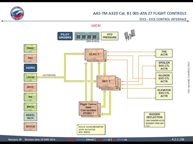
- 155. EFCS CONTROL INTERFACE LGCIU The Landing Gear Control and Interface Units (LGCIUs) transmit L/G position information
- 156. EFCS - EFCS CONTROL INTERFACE LGCIU
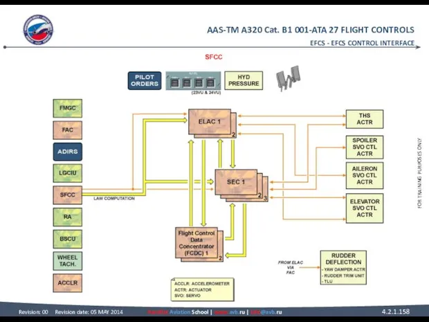
- 157. EFCS CONTROL INTERFACE SFCC The Slat Flap Control Computers (SFCCs) transmit slat flap surface position to
- 158. EFCS - EFCS CONTROL INTERFACE SFCC
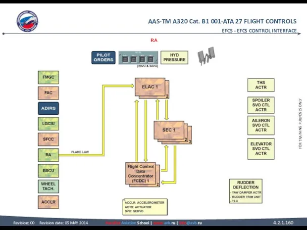
- 159. EFCS CONTROL INTERFACE RA The Radio Altimeter (RA) transmits the altitude information to the ELACs for
- 160. EFCS - EFCS CONTROL INTERFACE RA
- 161. EFCS CONTROL INTERFACE BSCU The BSCU receives information from the ELACs for the nose wheel steering
- 162. EFCS - EFCS CONTROL INTERFACE BSCU
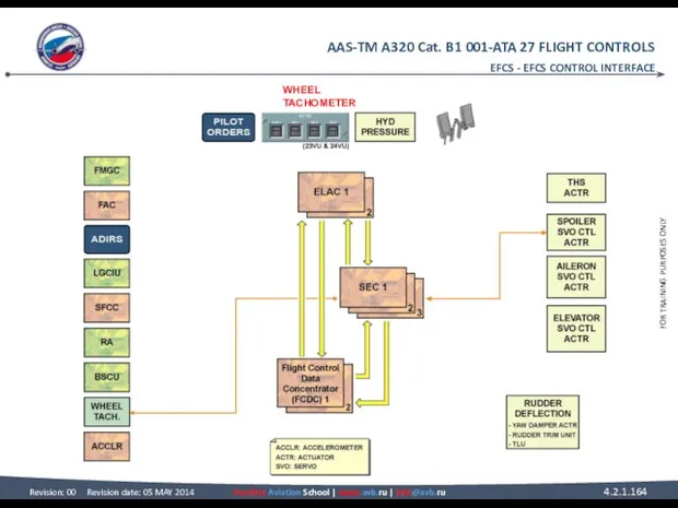
- 163. EFCS CONTROL INTERFACE WHEEL TACHOMETER Each MLG wheel speed is transmitted by wheel tachometers to the
- 164. EFCS - EFCS CONTROL INTERFACE WHEEL TACHOMETER
- 165. EFCS CONTROL INTERFACE ACCELEROMETER The vertical accelerometers, installed in the FWD cargo compartment, transmit the vertical
- 166. EFCS - EFCS CONTROL INTERFACE ACCELEROMETER
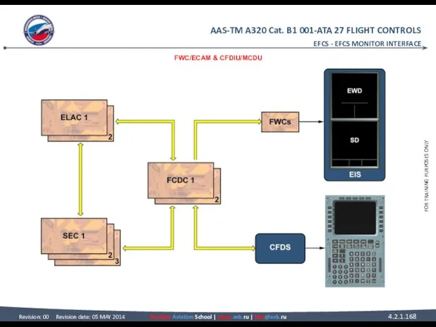
- 167. EFCS MONITOR INTERFACE FWC/ECAM The flight control system failures are sent to the Flight Warning Computers
- 168. EFCS - EFCS MONITOR INTERFACE FWC/ECAM & CFDIU/MCDU
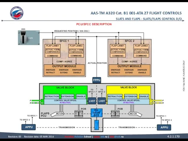
- 169. SLATS AND FLAPS SLATS/FLAPS CONTROL D/O PCU/SFCC DESCRIPTION This presentation shows the detailed operation of the
- 170. SLATS AND FLAPS - SLATS/FLAPS CONTROL D/O PCU/SFCC DESCRIPTION
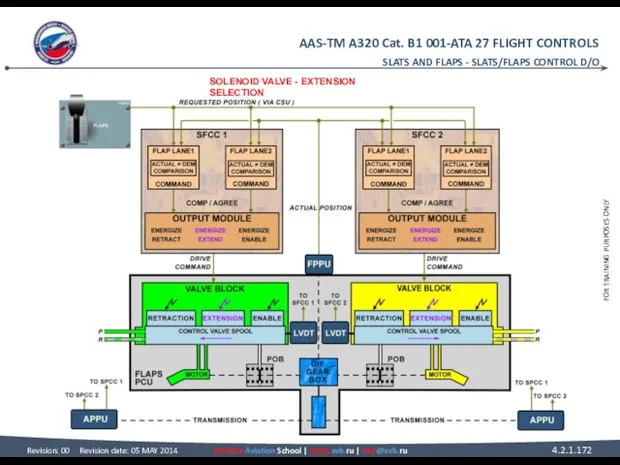
- 171. SLATS/FLAPS CONTROL D/O SOLENOID VALVE EXTENSION SELECTION Moving the slat flap lever rotates the Command Sensor
- 172. SLATS AND FLAPS - SLATS/FLAPS CONTROL D/O SOLENOID VALVE - EXTENSION SELECTION
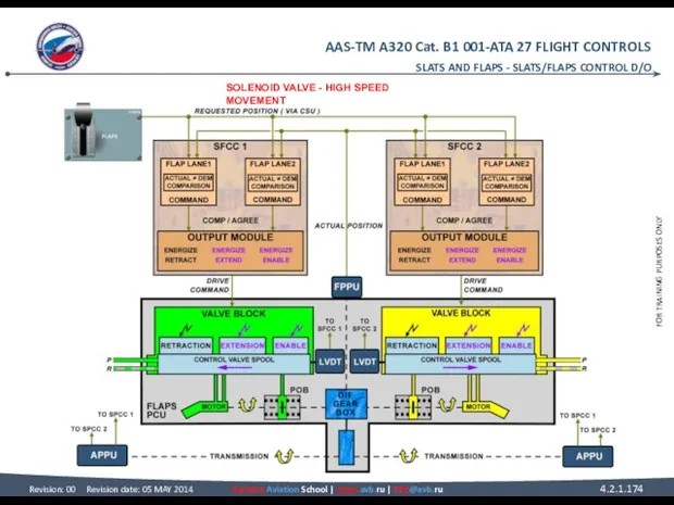
- 173. SLATS/FLAPS CONTROL D/O SOLENOID VALVE (continued) HIGH SPEED MOVEMENT The enable solenoid valve is energized to
- 174. SLATS AND FLAPS - SLATS/FLAPS CONTROL D/O SOLENOID VALVE - HIGH SPEED MOVEMENT
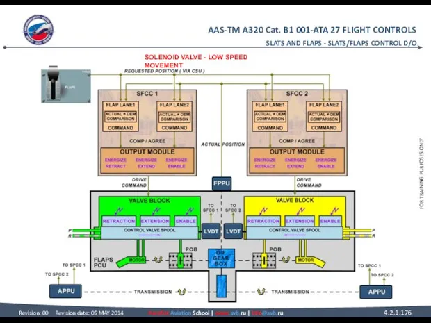
- 175. SLATS/FLAPS CONTROL D/O SOLENOID VALVE (continued) LOW SPEED MOVEMENT As the flap approaches the requested position,
- 176. SLATS AND FLAPS - SLATS/FLAPS CONTROL D/O SOLENOID VALVE - LOW SPEED MOVEMENT
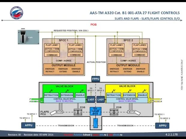
- 177. SLATS/FLAPS CONTROL D/O POB When the flaps reach the requested position, all solenoid valves are de-energized
- 178. SLATS AND FLAPS - SLATS/FLAPS CONTROL D/O POB
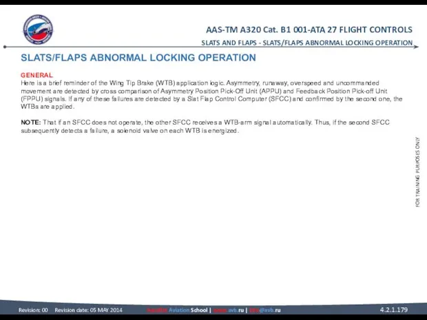
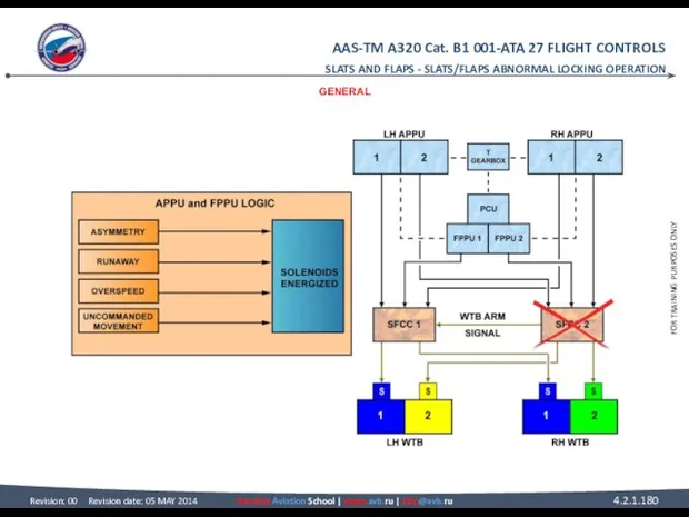
- 179. SLATS/FLAPS ABNORMAL LOCKING OPERATION GENERAL Here is a brief reminder of the Wing Tip Brake (WTB)
- 180. SLATS AND FLAPS - SLATS/FLAPS ABNORMAL LOCKING OPERATION GENERAL
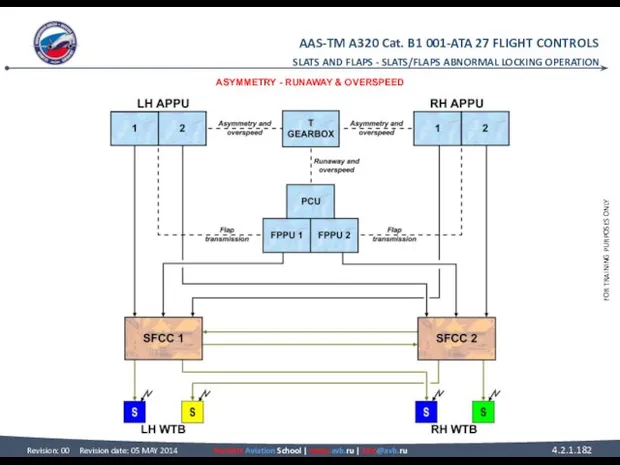
- 181. SLATS/FLAPS ABNORMAL LOCKING OPERATION ASYMMETRY Asymmetry is defined as a positional difference between the LH and
- 182. SLATS AND FLAPS - SLATS/FLAPS ABNORMAL LOCKING OPERATION ASYMMETRY - RUNAWAY & OVERSPEED
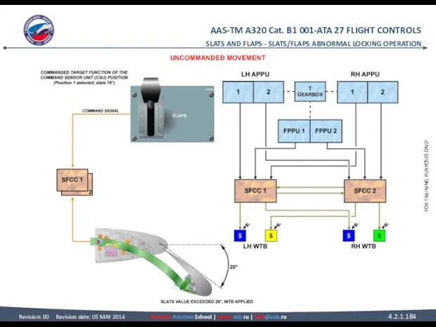
- 183. SLATS/FLAPS ABNORMAL LOCKING OPERATION UNCOMMANDED MOVEMENT Uncommanded movement is defined as a movement away from the
- 184. SLATS AND FLAPS - SLATS/FLAPS ABNORMAL LOCKING OPERATION UNCOMMANDED MOVEMENT
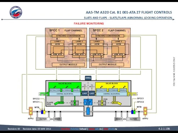
- 185. SLATS/FLAPS ABNORMAL LOCKING OPERATION FAILURE MONITORING If PCUs are in operation, extended solenoid and enable solenoid
- 186. SLATS AND FLAPS - SLATS/FLAPS ABNORMAL LOCKING OPERATION FAILURE MONITORING
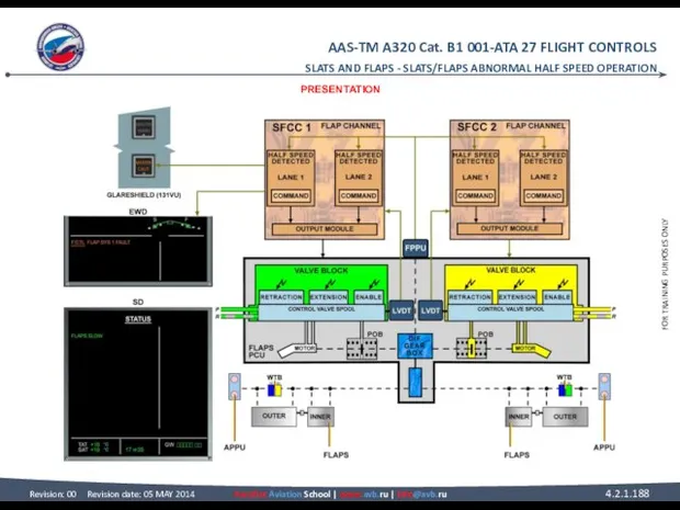
- 187. SLATS/FLAPS ABNORMAL HALF SPEED OPERATION PRESENTATION We will study examples on abnormal operations which cause the
- 188. SLATS AND FLAPS - SLATS/FLAPS ABNORMAL HALF SPEED OPERATION PRESENTATION
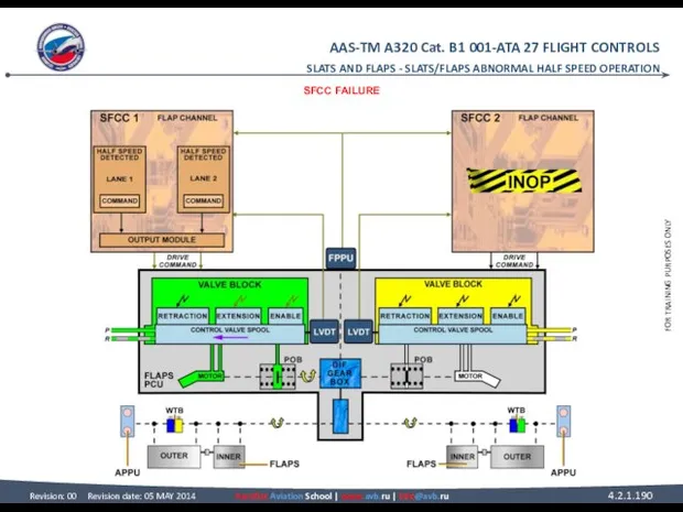
- 189. SLATS/FLAPS ABNORMAL HALF SPEED OPERATION SFCC FAILURE In this example Slat Flap Control Computer (SFCC) 2
- 190. SLATS AND FLAPS - SLATS/FLAPS ABNORMAL HALF SPEED OPERATION SFCC FAILURE
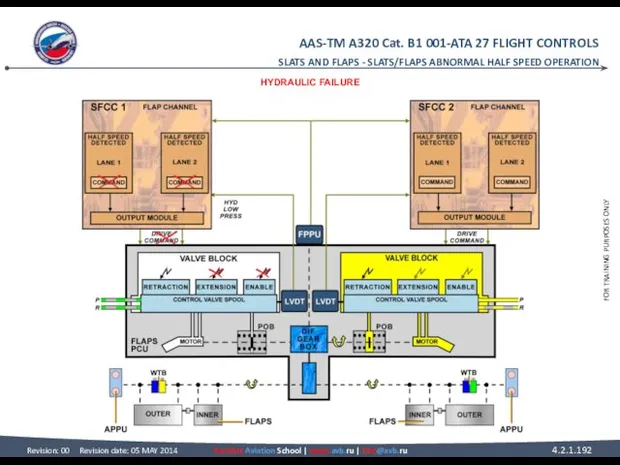
- 191. SLATS/FLAPS ABNORMAL HALF SPEED OPERATION HYDRAULIC FAILURE Each SFCC channel monitors the hydraulic pressure for its
- 192. SLATS AND FLAPS - SLATS/FLAPS ABNORMAL HALF SPEED OPERATION HYDRAULIC FAILURE
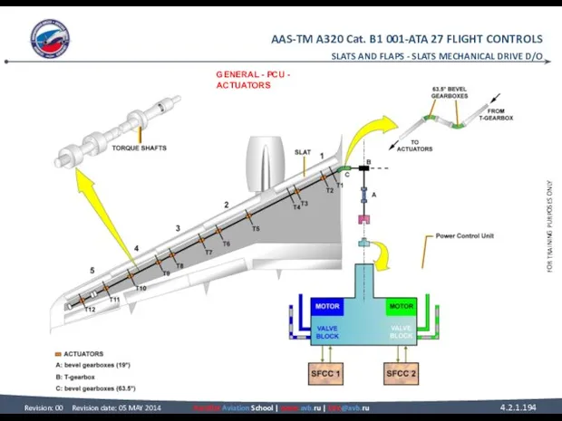
- 193. SLATS MECHANICAL DRIVE D/O GENERAL Torque shafts and gearboxes transmit power from the Power Control Unit
- 194. SLATS AND FLAPS - SLATS MECHANICAL DRIVE D/O GENERAL - PCU - ACTUATORS
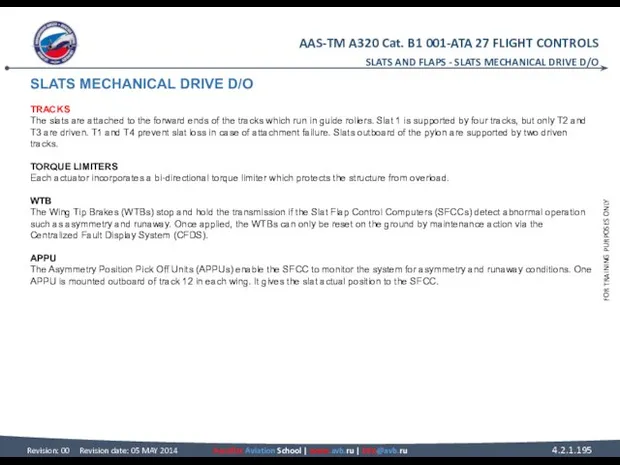
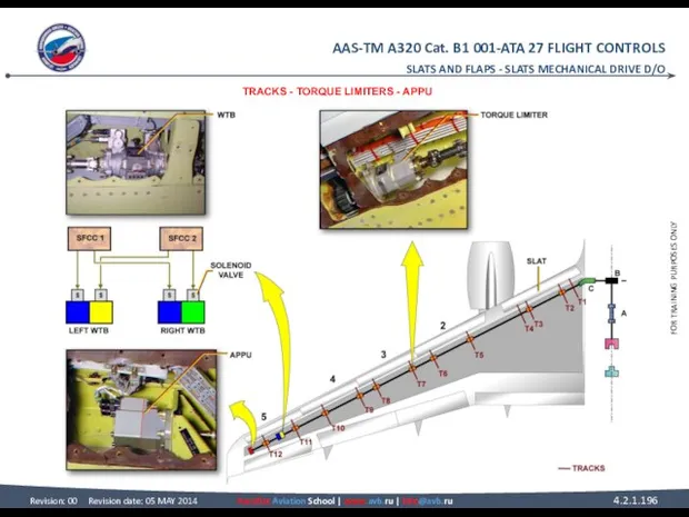
- 195. SLATS MECHANICAL DRIVE D/O TRACKS The slats are attached to the forward ends of the tracks
- 196. SLATS AND FLAPS - SLATS MECHANICAL DRIVE D/O TRACKS - TORQUE LIMITERS - APPU
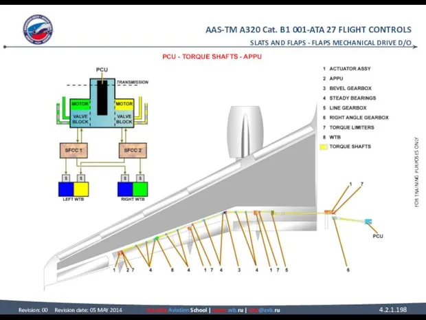
- 197. FLAPS MECHANICAL DRIVE D/O PCU The Power Control Unit (PCU) incorporates two hydraulic motors, each one
- 198. SLATS AND FLAPS - FLAPS MECHANICAL DRIVE D/O PCU - TORQUE SHAFTS - APPU
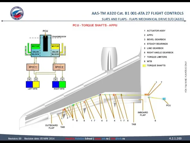
- 199. FLAPS MECHANICAL DRIVE D/O (A321) PCU The Power Control Unit (PCU) incorporates two hydraulic motors, each
- 200. SLATS AND FLAPS - FLAPS MECHANICAL DRIVE D/O (A321) PCU - TORQUE SHAFTS - APPU
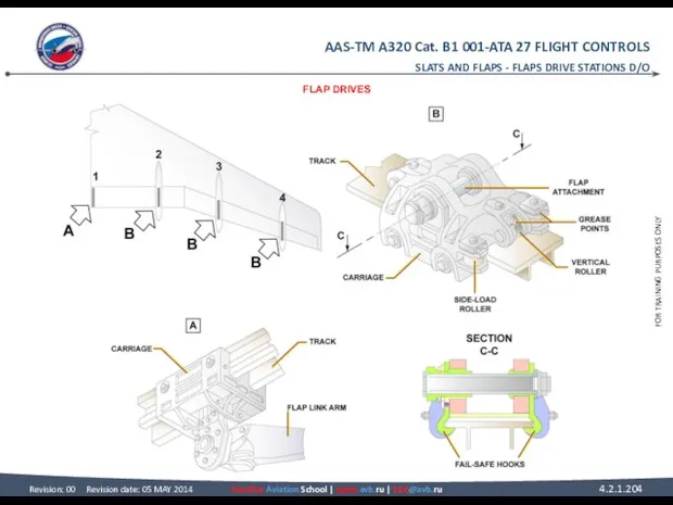
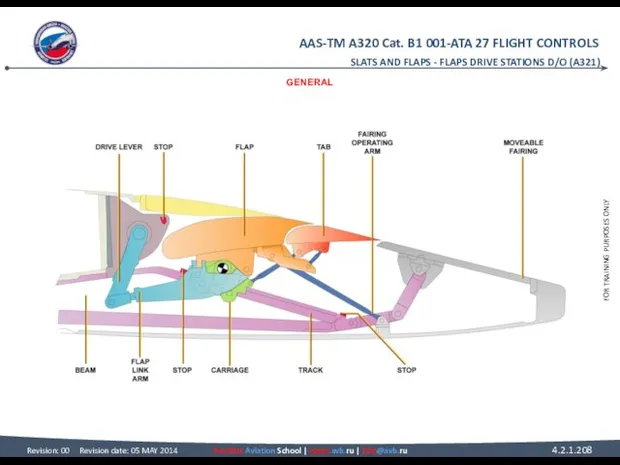
- 201. FLAPS DRIVE STATIONS D/O GENERAL Each flap is supported by carriages that run on tracks extending
- 202. SLATS AND FLAPS - FLAPS DRIVE STATIONS D/O GENERAL
- 203. FLAPS DRIVE STATIONS D/O FLAP DRIVES Carriage 1 is held below the track and travels on
- 204. SLATS AND FLAPS - FLAPS DRIVE STATIONS D/O FLAP DRIVES
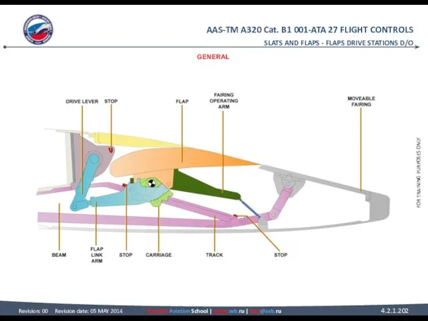
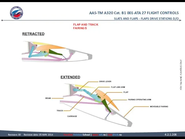
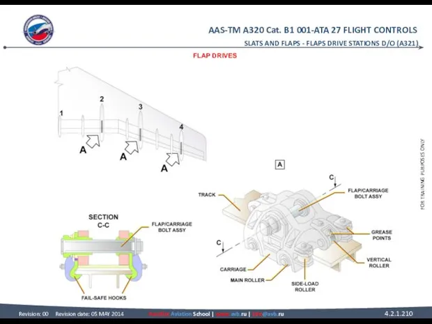
- 205. FLAPS DRIVE STATIONS D/O FLAP AND TRACK FAIRINGS A flap link arm is attached to the
- 206. SLATS AND FLAPS - FLAPS DRIVE STATIONS D/O FLAP AND TRACK FAIRINGS
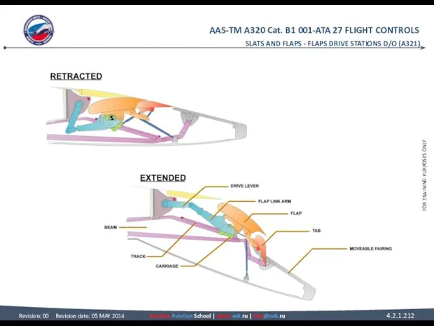
- 207. FLAPS DRIVE STATIONS D/O (A321) GENERAL Each flap is supported by carriages that run on tracks
- 208. SLATS AND FLAPS - FLAPS DRIVE STATIONS D/O (A321) GENERAL
- 209. FLAPS DRIVE STATIONS D/O (A321) FLAP DRIVES Six vertical-load and four side-load rollers hold each carriage
- 210. SLATS AND FLAPS - FLAPS DRIVE STATIONS D/O (A321) FLAP DRIVES
- 211. FLAPS DRIVE STATIONS D/O (A321) FLAP AND TRACK FAIRINGS A flap link arm is attached to
- 212. SLATS AND FLAPS - FLAPS DRIVE STATIONS D/O (A321)
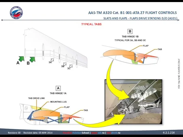
- 213. FLAPS DRIVE STATIONS D/O (A321) TYPICAL TABS The inner tab is attached to the rear spar
- 214. SLATS AND FLAPS - FLAPS DRIVE STATIONS D/O (A321) TYPICAL TABS
- 215. FLAPS DRIVE STATIONS D/O (A321) A321 FIELD TRIP SLATS AND FLAPS - FLAPS DRIVE STATIONS D/O
- 216. SLATS AND FLAPS - FLAPS DRIVE STATIONS D/O (A321) A321 FIELD TRIP
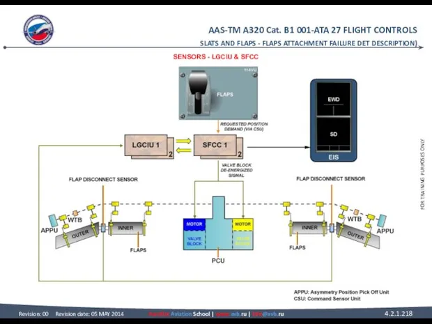
- 217. FLAPS ATTACHMENT FAILURE DET DESCRIPTION SENSORS Two flap disconnect sensors are fitted on the interconnecting strut
- 218. SLATS AND FLAPS - FLAPS ATTACHMENT FAILURE DET DESCRIPTION) SENSORS - LGCIU & SFCC
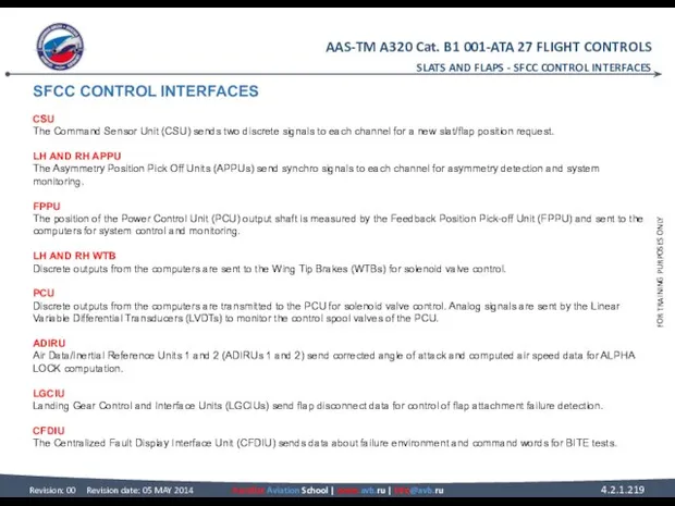
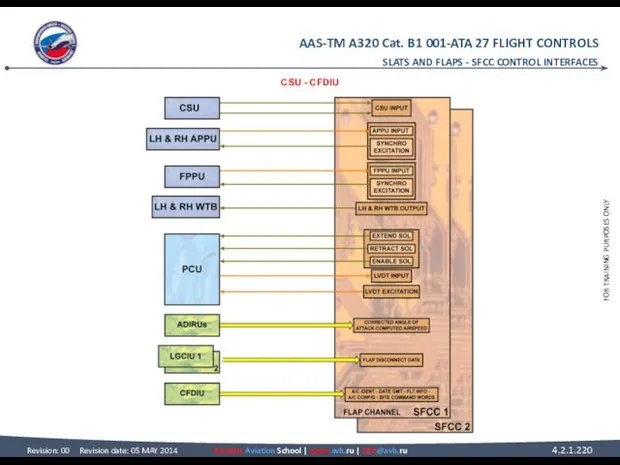
- 219. SFCC CONTROL INTERFACES CSU The Command Sensor Unit (CSU) sends two discrete signals to each channel
- 220. SLATS AND FLAPS - SFCC CONTROL INTERFACES CSU - CFDIU
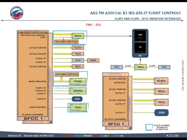
- 221. SFCC MONITOR INTERFACES FWC The Instrumentation Position Pick-off Units (IPPUs) supply slat/flap position data to the
- 222. ADIRU Flap position data are used by the Air Data/Inertial Reference Units (ADIRUs) for Angle-Of-Attack (AOA)
- 223. FWC - EIU SLATS AND FLAPS - SFCC MONITOR INTERFACES
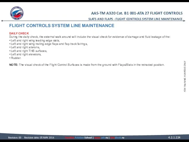
- 224. FLIGHT CONTROLS SYSTEM LINE MAINTENANCE DAILY CHECK During the daily check, the external walk around will
- 225. SLATS AND FLAPS - FLIGHT CONTROLS SYSTEM LINE MAINTENANCE DAILY CHECK
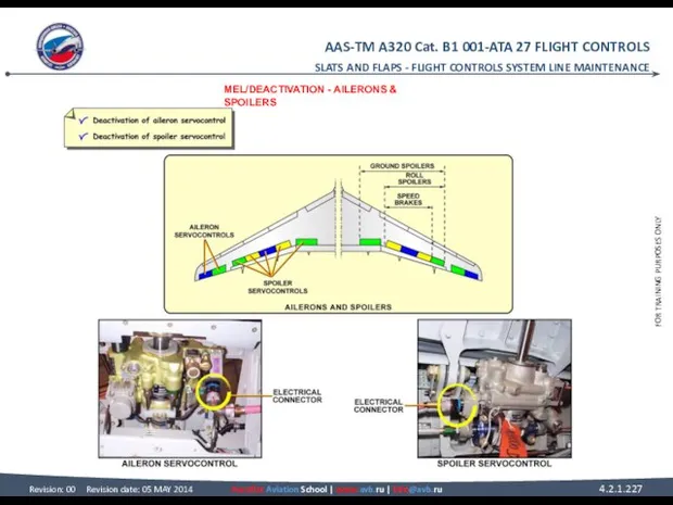
- 226. FLIGHT CONTROLS SYSTEM LINE MAINTENANCE MEL/DEACTIVATION AILERONS As aileron servocontrol is a MMEL item, the deactivation
- 227. SLATS AND FLAPS - FLIGHT CONTROLS SYSTEM LINE MAINTENANCE MEL/DEACTIVATION - AILERONS & SPOILERS
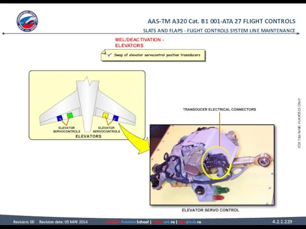
- 228. FLIGHT CONTROLS SYSTEM LINE MAINTENANCE MEL/DEACTIVATION (continued) ELEVATORS The elevator servocontrol position transducer (XDCR) is a
- 229. SLATS AND FLAPS - FLIGHT CONTROLS SYSTEM LINE MAINTENANCE MEL/DEACTIVATION - ELEVATORS
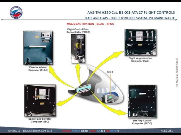
- 230. FLIGHT CONTROLS SYSTEM LINE MAINTENANCE MEL/DEACTIVATION (continued) ELAC There are two ELACs (ELAC 1 and 2).
- 231. SLATS AND FLAPS - FLIGHT CONTROLS SYSTEM LINE MAINTENANCE MEL/DEACTIVATION - ELAC - SFCC
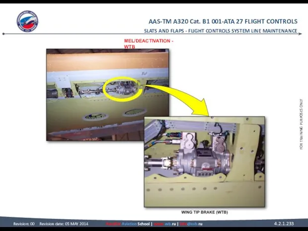
- 232. FLIGHT CONTROLS SYSTEM LINE MAINTENANCE MEL/DEACTIVATION (continued) WTB On SLAT or FLAP WTBs, one or two
- 233. SLATS AND FLAPS - FLIGHT CONTROLS SYSTEM LINE MAINTENANCE MEL/DEACTIVATION - WTB
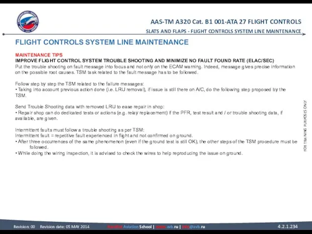
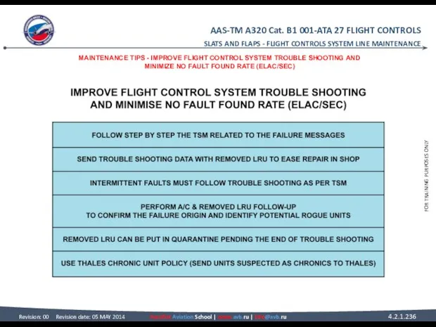
- 234. FLIGHT CONTROLS SYSTEM LINE MAINTENANCE MAINTENANCE TIPS IMPROVE FLIGHT CONTROL SYSTEM TROUBLE SHOOTING AND MINIMIZE NO
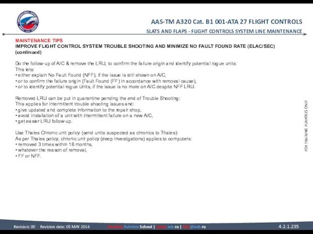
- 235. MAINTENANCE TIPS IMPROVE FLIGHT CONTROL SYSTEM TROUBLE SHOOTING AND MINIMIZE NO FAULT FOUND RATE (ELAC/SEC) (continued)
- 236. SLATS AND FLAPS - FLIGHT CONTROLS SYSTEM LINE MAINTENANCE MAINTENANCE TIPS - IMPROVE FLIGHT CONTROL SYSTEM
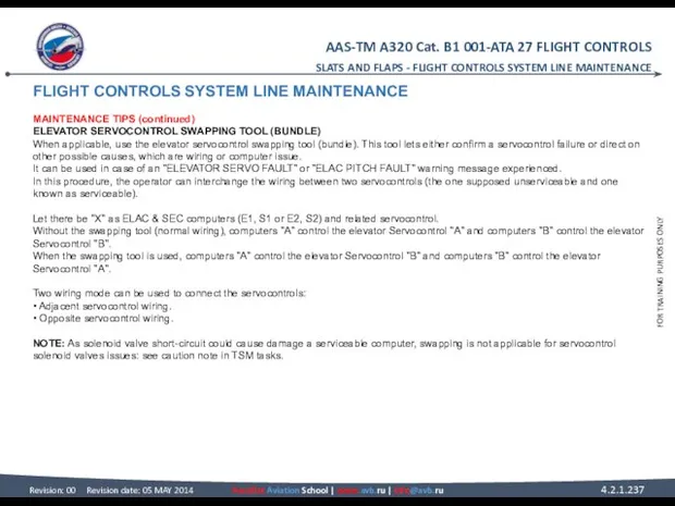
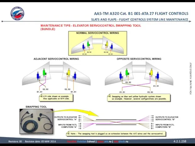
- 237. FLIGHT CONTROLS SYSTEM LINE MAINTENANCE MAINTENANCE TIPS (continued) ELEVATOR SERVOCONTROL SWAPPING TOOL (BUNDLE) When applicable, use
- 238. SLATS AND FLAPS - FLIGHT CONTROLS SYSTEM LINE MAINTENANCE MAINTENANCE TIPS - ELEVATOR SERVOCONTROL SWAPPING TOOL
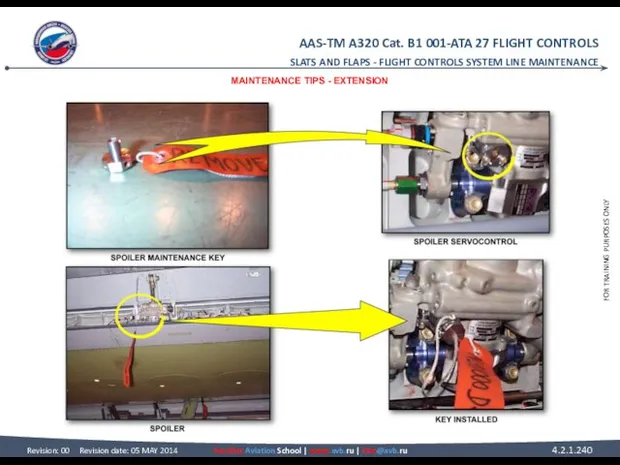
- 239. FLIGHT CONTROLS SYSTEM LINE MAINTENANCE MAINTENANCE TIPS (continued) EXTENSION To be unlocked, the servo control actuator
- 240. SLATS AND FLAPS - FLIGHT CONTROLS SYSTEM LINE MAINTENANCE MAINTENANCE TIPS - EXTENSION
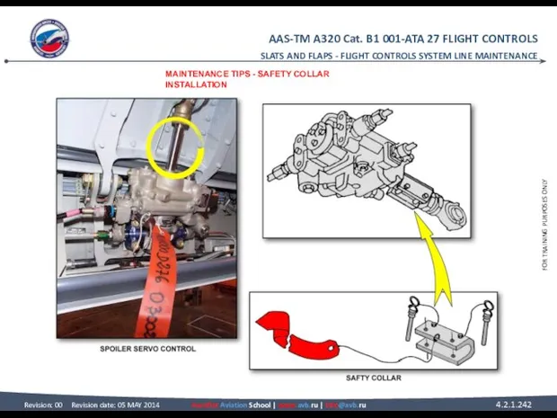
- 241. FLIGHT CONTROLS SYSTEM LINE MAINTENANCE MAINTENANCE TIPS (continued) SAFETY COLLAR INSTALLATION Once the maintenance-unlocking device is
- 242. SLATS AND FLAPS - FLIGHT CONTROLS SYSTEM LINE MAINTENANCE MAINTENANCE TIPS - SAFETY COLLAR INSTALLATION
- 243. FLIGHT CONTROLS SYSTEM LINE MAINTENANCE MAINTENANCE TIPS (continued) RETRACTION To retract the spoiler, the Safety Collar
- 245. Скачать презентацию
ATA 27 FLIGHT CONTROLS
GENERAL
Flight Controls System Component Location....................................................
Side Stick Description/Operation......................................................................
Flight Control
ATA 27 FLIGHT CONTROLS
GENERAL
Flight Controls System Component Location....................................................
Side Stick Description/Operation......................................................................
Flight Control
GENERAL
FLIGHT CONTROLS SYSTEM COMPONENT LOCATION
SYSTEM OVERVIEW
The control is achieved through the
GENERAL FLIGHT CONTROLS SYSTEM COMPONENT LOCATION SYSTEM OVERVIEW The control is achieved through the
GENERAL - FLIGHT CONTROLS SYSTEM COMPONENT LOCATION
SYSTEM OVERVIEW – PITCH -
GENERAL - FLIGHT CONTROLS SYSTEM COMPONENT LOCATION
SYSTEM OVERVIEW – PITCH -
FLIGHT CONTROLS SYSTEM COMPONENT LOCATION
SYSTEM OVERVIEW (continued)
HIGH LIFT
Slats and flaps achieve
FLIGHT CONTROLS SYSTEM COMPONENT LOCATION SYSTEM OVERVIEW (continued) HIGH LIFT Slats and flaps achieve
GENERAL - FLIGHT CONTROLS SYSTEM COMPONENT LOCATION
SYSTEM OVERVIEW - HIGH LIFT
GENERAL - FLIGHT CONTROLS SYSTEM COMPONENT LOCATION
SYSTEM OVERVIEW - HIGH LIFT
GENERAL - FLIGHT CONTROLS SYSTEM COMPONENT LOCATION
SYSTEM OVERVIEW - HIGH LIFT
GENERAL - FLIGHT CONTROLS SYSTEM COMPONENT LOCATION
SYSTEM OVERVIEW - HIGH LIFT
FLIGHT CONTROLS SYSTEM COMPONENT LOCATION
SYSTEM OVERVIEW (continued)
COMPUTERS
A computer arrangement permanently controls
FLIGHT CONTROLS SYSTEM COMPONENT LOCATION SYSTEM OVERVIEW (continued) COMPUTERS A computer arrangement permanently controls
GENERAL - FLIGHT CONTROLS SYSTEM COMPONENT LOCATION
SYSTEM OVERVIEW - COMPUTERS
GENERAL - FLIGHT CONTROLS SYSTEM COMPONENT LOCATION
SYSTEM OVERVIEW - COMPUTERS
FLIGHT CONTROLS SYSTEM COMPONENT LOCATION
SYSTEM OVERVIEW (continued)
ACTIVE SERVO CONTROLS
There are two
FLIGHT CONTROLS SYSTEM COMPONENT LOCATION SYSTEM OVERVIEW (continued) ACTIVE SERVO CONTROLS There are two
GENERAL - FLIGHT CONTROLS SYSTEM COMPONENT LOCATION
SYSTEM OVERVIEW - ACTIVE SERVO
GENERAL - FLIGHT CONTROLS SYSTEM COMPONENT LOCATION
SYSTEM OVERVIEW - ACTIVE SERVO
FLIGHT CONTROLS SYSTEM COMPONENT LOCATION
COMPONENT LOCATION
COMPUTERS
All the flight control computers
FLIGHT CONTROLS SYSTEM COMPONENT LOCATION COMPONENT LOCATION COMPUTERS All the flight control computers
GENERAL - FLIGHT CONTROLS SYSTEM COMPONENT LOCATION
COMPONENT LOCATION - COMPUTERS
GENERAL - FLIGHT CONTROLS SYSTEM COMPONENT LOCATION
COMPONENT LOCATION - COMPUTERS
SIDE STICK DESCRIPTION/OPERATION
GENERAL
The main function of the side sticks is to
SIDE STICK DESCRIPTION/OPERATION GENERAL The main function of the side sticks is to
GENERAL - SIDE STICK DESCRIPTION/OPERATION
GENERAL
GENERAL - SIDE STICK DESCRIPTION/OPERATION
GENERAL
SIDE STICK DESCRIPTION/OPERATION
SIDE STICK AND PRIORITY LOGIC
Side sticks, one on each
SIDE STICK DESCRIPTION/OPERATION SIDE STICK AND PRIORITY LOGIC Side sticks, one on each
GENERAL - SIDE STICK DESCRIPTION/OPERATION
SIDE STICK AND PRIORITY LOGIC
GENERAL - SIDE STICK DESCRIPTION/OPERATION
SIDE STICK AND PRIORITY LOGIC
FLIGHT CONTROL LAWS
PRINCIPLE
A side stick or an autopilot sends an electrical
FLIGHT CONTROL LAWS PRINCIPLE A side stick or an autopilot sends an electrical
GENERAL - FLIGHT CONTROL LAWS
PRINCIPLE
GENERAL - FLIGHT CONTROL LAWS
PRINCIPLE
GENERAL - FLIGHT CONTROL LAWS
PRINCIPLE
GENERAL - FLIGHT CONTROL LAWS
PRINCIPLE
FLIGHT CONTROL LAWS
NORMAL LAW
Normal law provides a number of airborne pitch
FLIGHT CONTROL LAWS NORMAL LAW Normal law provides a number of airborne pitch
GENERAL - FLIGHT CONTROL LAWS
NORMAL LAW - LOAD FACTOR LIMITATION
GENERAL - FLIGHT CONTROL LAWS
NORMAL LAW - LOAD FACTOR LIMITATION
FLIGHT CONTROL LAWS
NORMAL LAW (continued)
PITCH ATTITUDE PROTECTION
If the aircraft reaches the
FLIGHT CONTROL LAWS NORMAL LAW (continued) PITCH ATTITUDE PROTECTION If the aircraft reaches the
GENERAL - FLIGHT CONTROL LAWS
NORMAL LAW - PITCH ATTITUDE PROTECTION
GENERAL - FLIGHT CONTROL LAWS
NORMAL LAW - PITCH ATTITUDE PROTECTION
FLIGHT CONTROL LAWS
NORMAL LAW (continued)
HIGH ANGLE OF ATTACK PROTECTION
The high Angle
FLIGHT CONTROL LAWS NORMAL LAW (continued) HIGH ANGLE OF ATTACK PROTECTION The high Angle
NORMAL LAW (continued)
HIGH ANGLE OF ATTACK PROTECTION (continued)
With autothrust inoperative or
NORMAL LAW (continued) HIGH ANGLE OF ATTACK PROTECTION (continued) With autothrust inoperative or
GENERAL - FLIGHT CONTROL LAWS
NORMAL LAW - HIGH ANGLE OF ATTACK
GENERAL - FLIGHT CONTROL LAWS
NORMAL LAW - HIGH ANGLE OF ATTACK
GENERAL - FLIGHT CONTROL LAWS
NORMAL LAW - HIGH ANGLE OF ATTACK
GENERAL - FLIGHT CONTROL LAWS
NORMAL LAW - HIGH ANGLE OF ATTACK

GENERAL - FLIGHT CONTROL LAWS
NORMAL LAW - HIGH ANGLE OF ATTACK
GENERAL - FLIGHT CONTROL LAWS
NORMAL LAW - HIGH ANGLE OF ATTACK
FLIGHT CONTROL LAWS
NORMAL LAW (continued)
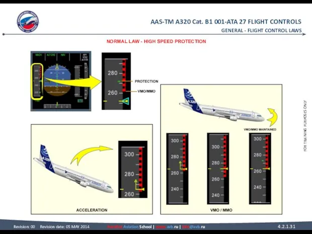
HIGH SPEED PROTECTION
The high speed protection is
FLIGHT CONTROL LAWS NORMAL LAW (continued) HIGH SPEED PROTECTION The high speed protection is
GENERAL - FLIGHT CONTROL LAWS
NORMAL LAW - HIGH SPEED PROTECTION
GENERAL - FLIGHT CONTROL LAWS
NORMAL LAW - HIGH SPEED PROTECTION
FLIGHT CONTROL LAWS
NORMAL LAW (continued)
BANK ANGLE PROTECTION
Under normal law, bank angle
FLIGHT CONTROL LAWS NORMAL LAW (continued) BANK ANGLE PROTECTION Under normal law, bank angle
GENERAL - FLIGHT CONTROL LAWS
NORMAL LAW - BANK ANGLE PROTECTION
GENERAL - FLIGHT CONTROL LAWS
NORMAL LAW - BANK ANGLE PROTECTION
ROLL/YAW
ROLL CONTROL NORMAL D/O
SIDESTICK
The sidestick sends electrical orders to the ELevator
ROLL/YAW ROLL CONTROL NORMAL D/O SIDESTICK The sidestick sends electrical orders to the ELevator
SPOILERS
Each spoiler is powered by one hydraulic actuator. Surfaces are automatically
SPOILERS Each spoiler is powered by one hydraulic actuator. Surfaces are automatically
ROLL/YAW - ROLL CONTROL NORMAL D/O
SIDESTICK - SPOILERS
ROLL/YAW - ROLL CONTROL NORMAL D/O
SIDESTICK - SPOILERS
ROLL CONTROL ABNORMAL OPERATION
COMPUTER FAILURES
A computer failure can engage a
ROLL CONTROL ABNORMAL OPERATION COMPUTER FAILURES A computer failure can engage a
ROLL/YAW - ROLL CONTROL ABNORMAL OPERATION
COMPUTER FAILURES - ELAC 1
ROLL/YAW - ROLL CONTROL ABNORMAL OPERATION
COMPUTER FAILURES - ELAC 1
ROLL CONTROL ABNORMAL OPERATION
COMPUTER FAILURES (continued)
ELAC 1+2 FAILURE
In case of
ROLL CONTROL ABNORMAL OPERATION COMPUTER FAILURES (continued) ELAC 1+2 FAILURE In case of
ROLL/YAW - ROLL CONTROL ABNORMAL OPERATION
COMPUTER FAILURES - ELAC 1+2
ROLL/YAW - ROLL CONTROL ABNORMAL OPERATION
COMPUTER FAILURES - ELAC 1+2
ROLL CONTROL ABNORMAL OPERATION
SERVO CONTROL FAILURES
AILERON SERVO CONTROL FAILURE
In case
ROLL CONTROL ABNORMAL OPERATION SERVO CONTROL FAILURES AILERON SERVO CONTROL FAILURE In case
ROLL/YAW - ROLL CONTROL ABNORMAL OPERATION
SERVO CONTROL FAILURES - AILERON
ROLL/YAW - ROLL CONTROL ABNORMAL OPERATION
SERVO CONTROL FAILURES - AILERON
ROLL CONTROL ABNORMAL OPERATION
SERVO CONTROL FAILURES (continued)
ELAC 1 SERVO CONTROLS
ROLL CONTROL ABNORMAL OPERATION SERVO CONTROL FAILURES (continued) ELAC 1 SERVO CONTROLS
ROLL/YAW - ROLL CONTROL ABNORMAL OPERATION
SERVO CONTROL FAILURES - ELAC
ROLL/YAW - ROLL CONTROL ABNORMAL OPERATION
SERVO CONTROL FAILURES - ELAC
ROLL CONTROL ABNORMAL OPERATION
SERVO CONTROL FAILURES (continued)
FAILURES ON THE SAME
ROLL CONTROL ABNORMAL OPERATION SERVO CONTROL FAILURES (continued) FAILURES ON THE SAME
ROLL/YAW - ROLL CONTROL ABNORMAL OPERATION
SERVO CONTROL FAILURES - FAILURES
ROLL/YAW - ROLL CONTROL ABNORMAL OPERATION
SERVO CONTROL FAILURES - FAILURES
ROLL CONTROL ABNORMAL OPERATION
SERVO CONTROL FAILURES (continued)
SPOILER SERVO CONTROL FAILURE
In
ROLL CONTROL ABNORMAL OPERATION SERVO CONTROL FAILURES (continued) SPOILER SERVO CONTROL FAILURE In
ROLL/YAW - ROLL CONTROL ABNORMAL OPERATION
SERVO CONTROL FAILURES - SPOILER
ROLL/YAW - ROLL CONTROL ABNORMAL OPERATION
SERVO CONTROL FAILURES - SPOILER
ROLL CONTROL ABNORMAL OPERATION
ELECTRICAL FAILURE
In case of total electrical loss,
ROLL CONTROL ABNORMAL OPERATION ELECTRICAL FAILURE In case of total electrical loss,
ROLL/YAW - ROLL CONTROL ABNORMAL OPERATION
ELECTRICAL FAILURE
ROLL/YAW - ROLL CONTROL ABNORMAL OPERATION
ELECTRICAL FAILURE
YAW CONTROL NORMAL D/O
GENERAL
The yaw control is done by the rudder,
YAW CONTROL NORMAL D/O GENERAL The yaw control is done by the rudder,
ROLL/YAW - YAW CONTROL NORMAL D/O
GENERAL - RUDDER
ROLL/YAW - YAW CONTROL NORMAL D/O
GENERAL - RUDDER
YAW CONTROL NORMAL D/O
FMGC
When the autopilot is engaged, the Flight Management
YAW CONTROL NORMAL D/O FMGC When the autopilot is engaged, the Flight Management
ROLL/YAW - YAW CONTROL NORMAL D/O
FMGC & YAW DAMPING
ROLL/YAW - YAW CONTROL NORMAL D/O
FMGC & YAW DAMPING
YAW CONTROL NORMAL D/O
RUDDER TRIM
The rudder trim is achieved by one
YAW CONTROL NORMAL D/O RUDDER TRIM The rudder trim is achieved by one
ROLL/YAW - YAW CONTROL NORMAL D/O
RUDDER TRIM & RUDDER LIMITATION
ROLL/YAW - YAW CONTROL NORMAL D/O
RUDDER TRIM & RUDDER LIMITATION
YAW CONTROL ABNORMAL D/O
ALTERNATE LAW
The alternate yaw damper law computed in
YAW CONTROL ABNORMAL D/O ALTERNATE LAW The alternate yaw damper law computed in

ALTERNATE LAW & YAW MECHANICAL
ROLL/YAW - YAW CONTROL ABNORMAL D/O
ALTERNATE LAW & YAW MECHANICAL
ROLL/YAW - YAW CONTROL ABNORMAL D/O
AILERON SERVO CONTROL OPERATION
GENERAL
Each aileron is equipped with two identical electro-hydraulic
AILERON SERVO CONTROL OPERATION GENERAL Each aileron is equipped with two identical electro-hydraulic
ROLL/YAW - AILERON SERVO CONTROL OPERATION
GENERAL & ACTIVE MODE
ROLL/YAW - AILERON SERVO CONTROL OPERATION
GENERAL & ACTIVE MODE
AILERON SERVO CONTROL OPERATION
DAMPING MODE
In damping mode, the actuator follows the
AILERON SERVO CONTROL OPERATION DAMPING MODE In damping mode, the actuator follows the
ROLL/YAW - AILERON SERVO CONTROL OPERATION
DAMPING MODE & MAINTENANCE AND RIGGING
ROLL/YAW - AILERON SERVO CONTROL OPERATION
DAMPING MODE & MAINTENANCE AND RIGGING
SPOILER SERVO CONTROL OPERATION
ACTIVE MODE
In active mode the spoiler servo
SPOILER SERVO CONTROL OPERATION ACTIVE MODE In active mode the spoiler servo
ROLL/YAW - SPOILER SERVO CONTROL OPERATION
ACTIVE MODE
ROLL/YAW - SPOILER SERVO CONTROL OPERATION
ACTIVE MODE
SPOILER SERVO CONTROL OPERATION
BIASED MODE
The servo-control actuator is pressurized. Due
SPOILER SERVO CONTROL OPERATION BIASED MODE The servo-control actuator is pressurized. Due
ROLL/YAW - SPOILER SERVO CONTROL OPERATION
BIASED MODE
ROLL/YAW - SPOILER SERVO CONTROL OPERATION
BIASED MODE
SPOILER SERVO CONTROL OPERATION
LOCKED MODE
In locked mode, the hydraulic pressure
SPOILER SERVO CONTROL OPERATION LOCKED MODE In locked mode, the hydraulic pressure
ROLL/YAW - SPOILER SERVO CONTROL OPERATION
LOCKED MODE
ROLL/YAW - SPOILER SERVO CONTROL OPERATION
LOCKED MODE
SPOILER SERVO CONTROL OPERATION
MANUAL MODE
To be unlocked, the servo control
SPOILER SERVO CONTROL OPERATION MANUAL MODE To be unlocked, the servo control
ROLL/YAW - SPOILER SERVO CONTROL OPERATION
MANUAL MODE
ROLL/YAW - SPOILER SERVO CONTROL OPERATION
MANUAL MODE
RUDDER TRIM ACTUATOR
GENERAL
The rudder trim actuator is installed on the rudder
RUDDER TRIM ACTUATOR GENERAL The rudder trim actuator is installed on the rudder
ROLL/YAW - RUDDER TRIM ACTUATOR
GENERAL - DESCRIPTION/OPERATION
ROLL/YAW - RUDDER TRIM ACTUATOR
GENERAL - DESCRIPTION/OPERATION
RUDDER SERVO CONTROL OPERATION
ACTIVE MODE
When the rudder servo control actuator is
RUDDER SERVO CONTROL OPERATION ACTIVE MODE When the rudder servo control actuator is
ACTIVE MODE
ROLL/YAW - RUDDER SERVO CONTROL OPERATION
ACTIVE MODE
ROLL/YAW - RUDDER SERVO CONTROL OPERATION
RUDDER SERVO CONTROL OPERATION
DAMPING MODE
The rudder servo control actuator changes to
RUDDER SERVO CONTROL OPERATION DAMPING MODE The rudder servo control actuator changes to
DAMPING MODE
ROLL/YAW - RUDDER SERVO CONTROL OPERATION
DAMPING MODE
ROLL/YAW - RUDDER SERVO CONTROL OPERATION
RUDDER SERVO CONTROL OPERATION
JAMMED CONTROL VALVE
If the control valve jams, the
RUDDER SERVO CONTROL OPERATION JAMMED CONTROL VALVE If the control valve jams, the
ROLL/YAW - RUDDER SERVO CONTROL OPERATION
JAMMED CONTROL VALVE
ROLL/YAW - RUDDER SERVO CONTROL OPERATION
JAMMED CONTROL VALVE
RUDDER LIMITER OPERATION
LOW SPEED CONFIGURATION
Under 160 kts the stops are in
RUDDER LIMITER OPERATION LOW SPEED CONFIGURATION Under 160 kts the stops are in
ROLL/YAW - RUDDER LIMITER OPERATION
LOW SPEED CONFIGURATION - HIGH SPEED CONFIGURATION
ROLL/YAW - RUDDER LIMITER OPERATION
LOW SPEED CONFIGURATION - HIGH SPEED CONFIGURATION
RUDDER LIMITER OPERATION
TRAVEL LIMITATION UNIT
The mechanical design of the Travel Limitation
RUDDER LIMITER OPERATION TRAVEL LIMITATION UNIT The mechanical design of the Travel Limitation
ROLL/YAW - RUDDER LIMITER OPERATION
TRAVEL LIMITATION UNIT
ROLL/YAW - RUDDER LIMITER OPERATION
TRAVEL LIMITATION UNIT
RUDDER LIMITER OPERATION
FAC
If both FACs fail, the rudder travel limitation value
RUDDER LIMITER OPERATION FAC If both FACs fail, the rudder travel limitation value
ROLL/YAW - RUDDER LIMITER OPERATION
FAC
ROLL/YAW - RUDDER LIMITER OPERATION
FAC
YAW DAMPER SERVO ACTUATOR OPERATION
ACTIVE MODE
The actuator is in active mode
YAW DAMPER SERVO ACTUATOR OPERATION ACTIVE MODE The actuator is in active mode
ROLL/YAW - YAW DAMPER SERVO ACTUATOR OPERATION
ACTIVE MODE & MONITORING
ROLL/YAW - YAW DAMPER SERVO ACTUATOR OPERATION
ACTIVE MODE & MONITORING
YAW DAMPER SERVO ACTUATOR OPERATION
BYPASS MODE
BOTH SOLENOID VALVES DE-ENERGIZED
The two-solenoid valves
YAW DAMPER SERVO ACTUATOR OPERATION BYPASS MODE BOTH SOLENOID VALVES DE-ENERGIZED The two-solenoid valves
ROLL/YAW - YAW DAMPER SERVO ACTUATOR OPERATION
BYPASS MODE - BOTH SOLENOID
ROLL/YAW - YAW DAMPER SERVO ACTUATOR OPERATION
BYPASS MODE - BOTH SOLENOID
YAW DAMPER SERVO ACTUATOR OPERATION
BYPASS MODE (continued)
ONE SOLENOID VALVE DE-ENERGIZED ONLY
In
YAW DAMPER SERVO ACTUATOR OPERATION BYPASS MODE (continued) ONE SOLENOID VALVE DE-ENERGIZED ONLY In
ROLL/YAW - YAW DAMPER SERVO ACTUATOR OPERATION
BYPASS MODE - ONE SOLENOID
ROLL/YAW - YAW DAMPER SERVO ACTUATOR OPERATION
BYPASS MODE - ONE SOLENOID
YAW DAMPER SERVO ACTUATOR OPERATION
BYPASS MODE (continued)
HYDRAULIC FAILURE
With no hydraulic pressure,
YAW DAMPER SERVO ACTUATOR OPERATION BYPASS MODE (continued) HYDRAULIC FAILURE With no hydraulic pressure,
ROLL/YAW - YAW DAMPER SERVO ACTUATOR OPERATION
BYPASS MODE - HYDRAULIC FAILURE
ROLL/YAW - YAW DAMPER SERVO ACTUATOR OPERATION
BYPASS MODE - HYDRAULIC FAILURE
SPEED BRAKE & GROUND SPOILER D/O
SPEED BRAKE FUNCTION
The speed brake function
SPEED BRAKE & GROUND SPOILER D/O SPEED BRAKE FUNCTION The speed brake function
ROLL/YAW - SPEED BRAKE & GROUND SPOILER D/O
SPEED BRAKE FUNCTION
ROLL/YAW - SPEED BRAKE & GROUND SPOILER D/O
SPEED BRAKE FUNCTION
SPEED BRAKE & GROUND SPOILER D/O
SPEED BRAKE LOGIC
The speed brake control
SPEED BRAKE & GROUND SPOILER D/O SPEED BRAKE LOGIC The speed brake control
ROLL/YAW - SPEED BRAKE & GROUND SPOILER D/O
SPEED BRAKE LOGIC
ROLL/YAW - SPEED BRAKE & GROUND SPOILER D/O
SPEED BRAKE LOGIC
ROLL/YAW - SPEED BRAKE & GROUND SPOILER D/O
SPEED BRAKE & GROUND
ROLL/YAW - SPEED BRAKE & GROUND SPOILER D/O
SPEED BRAKE & GROUND
ROLL/YAW - SPEED BRAKE & GROUND SPOILER D/O
GROUND SPOILER FUNCTION
ROLL/YAW - SPEED BRAKE & GROUND SPOILER D/O
GROUND SPOILER FUNCTION
ROLL/YAW - SPEED BRAKE & GROUND SPOILER D/O
SPEED BRAKE & GROUND
ROLL/YAW - SPEED BRAKE & GROUND SPOILER D/O
SPEED BRAKE & GROUND
ROLL/YAW - SPEED BRAKE & GROUND SPOILER D/O
GROUND SPOILER LOGIC
ROLL/YAW - SPEED BRAKE & GROUND SPOILER D/O
GROUND SPOILER LOGIC
PITCH - PITCH CONTROL NORMAL D/O
PITCH
PITCH CONTROL NORMAL D/O
SIDE STICK
The
PITCH - PITCH CONTROL NORMAL D/O
PITCH PITCH CONTROL NORMAL D/O SIDE STICK The
SIDE STICK - TRIM WHEELS
PITCH - PITCH CONTROL NORMAL D/O
SIDE STICK - TRIM WHEELS
PITCH - PITCH CONTROL NORMAL D/O
PITCH CONTROL ABNORMAL D/O
ALTERNATE LAW
If the normal law of the ELevator
PITCH CONTROL ABNORMAL D/O ALTERNATE LAW If the normal law of the ELevator
PITCH - PITCH CONTROL ABNORMAL D/O
ALTERNATE LAW - IN ELAC
PITCH - PITCH CONTROL ABNORMAL D/O
ALTERNATE LAW - IN ELAC
PITCH - PITCH CONTROL ABNORMAL D/O
ALTERNATE LAW - IN ELAC
PITCH - PITCH CONTROL ABNORMAL D/O
ALTERNATE LAW - IN ELAC
PITCH CONTROL ABNORMAL D/O
ALTERNATE LAW (continued)
IN SEC
After a double ELAC failure,
PITCH CONTROL ABNORMAL D/O ALTERNATE LAW (continued) IN SEC After a double ELAC failure,
PITCH - PITCH CONTROL ABNORMAL D/O
ALTERNATE LAW - IN SEC
PITCH - PITCH CONTROL ABNORMAL D/O
ALTERNATE LAW - IN SEC
PITCH CONTROL ABNORMAL D/O
DIRECT LAW
If the alternate law is lost, the
PITCH CONTROL ABNORMAL D/O DIRECT LAW If the alternate law is lost, the
PITCH - PITCH CONTROL ABNORMAL D/O
DIRECT LAW
PITCH - PITCH CONTROL ABNORMAL D/O
DIRECT LAW
PITCH - PITCH CONTROL ABNORMAL D/O
DIRECT LAW
PITCH - PITCH CONTROL ABNORMAL D/O
DIRECT LAW
PITCH CONTROL ABNORMAL D/O
MECHANICAL BACK-UP
In case of total electrical failure or
PITCH CONTROL ABNORMAL D/O MECHANICAL BACK-UP In case of total electrical failure or
PITCH - PITCH CONTROL ABNORMAL D/O
MECHANICAL BACK-UP
PITCH - PITCH CONTROL ABNORMAL D/O
MECHANICAL BACK-UP
PITCH CONTROL ABNORMAL D/O
PITCH LAW RECONFIGURATION
This diagram summarizes the pitch law
PITCH CONTROL ABNORMAL D/O PITCH LAW RECONFIGURATION This diagram summarizes the pitch law
PITCH - PITCH CONTROL ABNORMAL D/O
PITCH LAW RECONFIGURATION
PITCH - PITCH CONTROL ABNORMAL D/O
PITCH LAW RECONFIGURATION
ELEVATOR SERVO CONTROL OPERATION
ACTIVE MODE
When the elevator servo control is in
ELEVATOR SERVO CONTROL OPERATION ACTIVE MODE When the elevator servo control is in
PITCH - ELEVATOR SERVO CONTROL OPERATION
ACTIVE MODE
PITCH - ELEVATOR SERVO CONTROL OPERATION
ACTIVE MODE
ELEVATOR SERVO CONTROL OPERATION
DAMPING MODE
In case of a computer failure (e.g.
ELEVATOR SERVO CONTROL OPERATION DAMPING MODE In case of a computer failure (e.g.
PITCH - ELEVATOR SERVO CONTROL OPERATION
DAMPING MODE
PITCH - ELEVATOR SERVO CONTROL OPERATION
DAMPING MODE
ELEVATOR SERVO CONTROL OPERATION
RE-CENTERING MODE
When the elevator servo control is in
ELEVATOR SERVO CONTROL OPERATION RE-CENTERING MODE When the elevator servo control is in
PITCH - ELEVATOR SERVO CONTROL OPERATION
RE-CENTERING MODE
PITCH - ELEVATOR SERVO CONTROL OPERATION
RE-CENTERING MODE
THS ACTUATOR OPERATION
THS DESCRIPTION
HYDRAULIC MOTORS
Both hydraulic motors drive the
THS ACTUATOR OPERATION THS DESCRIPTION HYDRAULIC MOTORS Both hydraulic motors drive the
PITCH - THS ACTUATOR OPERATION
THS DESCRIPTION - HYDRAULIC MOTORS -
PITCH - THS ACTUATOR OPERATION
THS DESCRIPTION - HYDRAULIC MOTORS -
THS ACTUATOR OPERATION
THS OPERATION
THS STATIC
In the Static mode:
• there
THS ACTUATOR OPERATION THS OPERATION THS STATIC In the Static mode: • there
PITCH - THS ACTUATOR OPERATION
THS OPERATION - THS STATIC
PITCH - THS ACTUATOR OPERATION
THS OPERATION - THS STATIC
THS ACTUATOR OPERATION
THS OPERATION (continued)
NORMAL OPERATION
ELAC2 (in normal control) sends
THS ACTUATOR OPERATION THS OPERATION (continued) NORMAL OPERATION ELAC2 (in normal control) sends

PITCH - THS ACTUATOR OPERATION
THS OPERATION - NORMAL OPERATION
PITCH - THS ACTUATOR OPERATION
THS OPERATION - NORMAL OPERATION

PITCH - THS ACTUATOR OPERATION
THS OPERATION - NORMAL OPERATION
PITCH - THS ACTUATOR OPERATION
THS OPERATION - NORMAL OPERATION

PITCH - THS ACTUATOR OPERATION
THS OPERATION - NORMAL OPERATION
PITCH - THS ACTUATOR OPERATION
THS OPERATION - NORMAL OPERATION
THS ACTUATOR OPERATION
THS OPERATION (continued)
OPERATION WITH ONE HYDRAULIC SYSTEM IN
THS ACTUATOR OPERATION THS OPERATION (continued) OPERATION WITH ONE HYDRAULIC SYSTEM IN
PITCH - THS ACTUATOR OPERATION
THS OPERATION - OPERATION WITH ONE
PITCH - THS ACTUATOR OPERATION
THS OPERATION - OPERATION WITH ONE

PITCH - THS ACTUATOR OPERATION
THS OPERATION - OPERATION WITH ONE
PITCH - THS ACTUATOR OPERATION
THS OPERATION - OPERATION WITH ONE

PITCH - THS ACTUATOR OPERATION
THS OPERATION - OPERATION WITH ONE
PITCH - THS ACTUATOR OPERATION
THS OPERATION - OPERATION WITH ONE
THS ACTUATOR OPERATION
THS OPERATION (continued)
THS MECHANICAL INPUT
A mechanical input link
THS ACTUATOR OPERATION THS OPERATION (continued) THS MECHANICAL INPUT A mechanical input link

PITCH - THS ACTUATOR OPERATION
THS OPERATION - THS MECHANICAL INPUT
PITCH - THS ACTUATOR OPERATION
THS OPERATION - THS MECHANICAL INPUT
PITCH - THS ACTUATOR OPERATION
THS OPERATION - THS MECHANICAL INPUT
PITCH - THS ACTUATOR OPERATION
THS OPERATION - THS MECHANICAL INPUT

PITCH - THS ACTUATOR OPERATION
THS OPERATION - THS MECHANICAL INPUT
PITCH - THS ACTUATOR OPERATION
THS OPERATION - THS MECHANICAL INPUT
THS ACTUATOR OPERATION
THS OPERATION (continued)
JAMMING MODE
ELAC2 (in normal control) sends
THS ACTUATOR OPERATION THS OPERATION (continued) JAMMING MODE ELAC2 (in normal control) sends

PITCH - THS ACTUATOR OPERATION
THS OPERATION - JAMMING MODE
PITCH - THS ACTUATOR OPERATION
THS OPERATION - JAMMING MODE

PITCH - THS ACTUATOR OPERATION
THS OPERATION - JAMMING MODE
PITCH - THS ACTUATOR OPERATION
THS OPERATION - JAMMING MODE
PITCH - THS ACTUATOR OPERATION
THS OPERATION - JAMMING MODE
PITCH - THS ACTUATOR OPERATION
THS OPERATION - JAMMING MODE
EFCS
EFCS CONTROL INTERFACE
PILOT ORDERS
The pilot orders like side stick, speed brake,
EFCS EFCS CONTROL INTERFACE PILOT ORDERS The pilot orders like side stick, speed brake,
EFCS - EFCS CONTROL INTERFACE
PILOT ORDERS
EFCS - EFCS CONTROL INTERFACE
PILOT ORDERS
EFCS CONTROL INTERFACE
FLIGHT CONTROL PANELS
P/Bs located on the FLighT ConTroL panels
EFCS CONTROL INTERFACE FLIGHT CONTROL PANELS P/Bs located on the FLighT ConTroL panels
EFCS - EFCS CONTROL INTERFACE
FLIGHT CONTROL PANELS
EFCS - EFCS CONTROL INTERFACE
FLIGHT CONTROL PANELS
EFCS CONTROL INTERFACE
HYDRAULIC PRESSURE
The hydraulic pressure status is sent to the
EFCS CONTROL INTERFACE HYDRAULIC PRESSURE The hydraulic pressure status is sent to the
EFCS - EFCS CONTROL INTERFACE
HYDRAULIC PRESSURE
EFCS - EFCS CONTROL INTERFACE
HYDRAULIC PRESSURE
EFCS CONTROL INTERFACE
RUDDER PEDAL POSITION
The signal from the rudder pedal transducers
EFCS CONTROL INTERFACE RUDDER PEDAL POSITION The signal from the rudder pedal transducers
EFCS - EFCS CONTROL INTERFACE
RUDDER PEDAL POSITION
EFCS - EFCS CONTROL INTERFACE
RUDDER PEDAL POSITION
EFCS CONTROL INTERFACE
FMGC
If the autopilot is active, pitch, roll and yaw
EFCS CONTROL INTERFACE FMGC If the autopilot is active, pitch, roll and yaw
EFCS - EFCS CONTROL INTERFACE
FMGC
EFCS - EFCS CONTROL INTERFACE
FMGC
EFCS CONTROL INTERFACE
FAC
The FACs receive rudder deflection information computed either by
EFCS CONTROL INTERFACE FAC The FACs receive rudder deflection information computed either by
EFCS - EFCS CONTROL INTERFACE
FAC
EFCS - EFCS CONTROL INTERFACE
FAC
EFCS CONTROL INTERFACE
ADIRS
The Air Data/Inertial Reference System (ADIRS) transmits air data
EFCS CONTROL INTERFACE ADIRS The Air Data/Inertial Reference System (ADIRS) transmits air data
EFCS - EFCS CONTROL INTERFACE
ADIRS
EFCS - EFCS CONTROL INTERFACE
ADIRS
EFCS CONTROL INTERFACE
LGCIU
The Landing Gear Control and Interface Units (LGCIUs) transmit
EFCS CONTROL INTERFACE LGCIU The Landing Gear Control and Interface Units (LGCIUs) transmit
EFCS - EFCS CONTROL INTERFACE
LGCIU
EFCS - EFCS CONTROL INTERFACE
LGCIU
EFCS CONTROL INTERFACE
SFCC
The Slat Flap Control Computers (SFCCs) transmit slat flap
EFCS CONTROL INTERFACE SFCC The Slat Flap Control Computers (SFCCs) transmit slat flap
EFCS - EFCS CONTROL INTERFACE
SFCC
EFCS - EFCS CONTROL INTERFACE
SFCC
EFCS CONTROL INTERFACE
RA
The Radio Altimeter (RA) transmits the altitude information to
EFCS CONTROL INTERFACE RA The Radio Altimeter (RA) transmits the altitude information to
EFCS - EFCS CONTROL INTERFACE
RA
EFCS - EFCS CONTROL INTERFACE
RA

EFCS CONTROL INTERFACE
BSCU
The BSCU receives information from the ELACs for the
EFCS CONTROL INTERFACE BSCU The BSCU receives information from the ELACs for the
EFCS - EFCS CONTROL INTERFACE
BSCU
EFCS - EFCS CONTROL INTERFACE
BSCU

EFCS CONTROL INTERFACE
WHEEL TACHOMETER
Each MLG wheel speed is transmitted by wheel
EFCS CONTROL INTERFACE WHEEL TACHOMETER Each MLG wheel speed is transmitted by wheel
EFCS - EFCS CONTROL INTERFACE
WHEEL TACHOMETER
EFCS - EFCS CONTROL INTERFACE
WHEEL TACHOMETER
EFCS CONTROL INTERFACE
ACCELEROMETER
The vertical accelerometers, installed in the FWD cargo compartment,
EFCS CONTROL INTERFACE ACCELEROMETER The vertical accelerometers, installed in the FWD cargo compartment,

EFCS - EFCS CONTROL INTERFACE
ACCELEROMETER
EFCS - EFCS CONTROL INTERFACE
ACCELEROMETER
EFCS MONITOR INTERFACE
FWC/ECAM
The flight control system failures are sent to the
EFCS MONITOR INTERFACE FWC/ECAM The flight control system failures are sent to the
EFCS - EFCS MONITOR INTERFACE
FWC/ECAM & CFDIU/MCDU
EFCS - EFCS MONITOR INTERFACE
FWC/ECAM & CFDIU/MCDU
SLATS AND FLAPS
SLATS/FLAPS CONTROL D/O
PCU/SFCC DESCRIPTION
This presentation shows the detailed operation
SLATS AND FLAPS SLATS/FLAPS CONTROL D/O PCU/SFCC DESCRIPTION This presentation shows the detailed operation
SLATS AND FLAPS - SLATS/FLAPS CONTROL D/O
PCU/SFCC DESCRIPTION
SLATS AND FLAPS - SLATS/FLAPS CONTROL D/O
PCU/SFCC DESCRIPTION
SLATS/FLAPS CONTROL D/O
SOLENOID VALVE
EXTENSION SELECTION
Moving the slat flap lever rotates
SLATS/FLAPS CONTROL D/O SOLENOID VALVE EXTENSION SELECTION Moving the slat flap lever rotates
SLATS AND FLAPS - SLATS/FLAPS CONTROL D/O
SOLENOID VALVE - EXTENSION SELECTION
SLATS AND FLAPS - SLATS/FLAPS CONTROL D/O
SOLENOID VALVE - EXTENSION SELECTION
SLATS/FLAPS CONTROL D/O
SOLENOID VALVE (continued)
HIGH SPEED MOVEMENT
The enable solenoid valve is
SLATS/FLAPS CONTROL D/O SOLENOID VALVE (continued) HIGH SPEED MOVEMENT The enable solenoid valve is
SLATS AND FLAPS - SLATS/FLAPS CONTROL D/O
SOLENOID VALVE - HIGH SPEED
SLATS AND FLAPS - SLATS/FLAPS CONTROL D/O
SOLENOID VALVE - HIGH SPEED
SLATS/FLAPS CONTROL D/O
SOLENOID VALVE (continued)
LOW SPEED MOVEMENT
As the flap approaches the
SLATS/FLAPS CONTROL D/O SOLENOID VALVE (continued) LOW SPEED MOVEMENT As the flap approaches the
SLATS AND FLAPS - SLATS/FLAPS CONTROL D/O
SOLENOID VALVE - LOW SPEED
SLATS AND FLAPS - SLATS/FLAPS CONTROL D/O
SOLENOID VALVE - LOW SPEED
SLATS/FLAPS CONTROL D/O
POB
When the flaps reach the requested position, all solenoid
SLATS/FLAPS CONTROL D/O POB When the flaps reach the requested position, all solenoid
SLATS AND FLAPS - SLATS/FLAPS CONTROL D/O
POB
SLATS AND FLAPS - SLATS/FLAPS CONTROL D/O
POB
SLATS/FLAPS ABNORMAL LOCKING OPERATION
GENERAL
Here is a brief reminder of the Wing
SLATS/FLAPS ABNORMAL LOCKING OPERATION GENERAL Here is a brief reminder of the Wing
SLATS AND FLAPS - SLATS/FLAPS ABNORMAL LOCKING OPERATION
GENERAL
SLATS AND FLAPS - SLATS/FLAPS ABNORMAL LOCKING OPERATION
GENERAL
SLATS/FLAPS ABNORMAL LOCKING OPERATION
ASYMMETRY
Asymmetry is defined as a positional difference between
SLATS/FLAPS ABNORMAL LOCKING OPERATION ASYMMETRY Asymmetry is defined as a positional difference between
SLATS AND FLAPS - SLATS/FLAPS ABNORMAL LOCKING OPERATION
ASYMMETRY - RUNAWAY &
SLATS AND FLAPS - SLATS/FLAPS ABNORMAL LOCKING OPERATION
ASYMMETRY - RUNAWAY &
SLATS/FLAPS ABNORMAL LOCKING OPERATION
UNCOMMANDED MOVEMENT
Uncommanded movement is defined as a movement
SLATS/FLAPS ABNORMAL LOCKING OPERATION UNCOMMANDED MOVEMENT Uncommanded movement is defined as a movement
SLATS AND FLAPS - SLATS/FLAPS ABNORMAL LOCKING OPERATION
UNCOMMANDED MOVEMENT
SLATS AND FLAPS - SLATS/FLAPS ABNORMAL LOCKING OPERATION
UNCOMMANDED MOVEMENT
SLATS/FLAPS ABNORMAL LOCKING OPERATION
FAILURE MONITORING
If PCUs are in operation, extended solenoid
SLATS/FLAPS ABNORMAL LOCKING OPERATION FAILURE MONITORING If PCUs are in operation, extended solenoid
SLATS AND FLAPS - SLATS/FLAPS ABNORMAL LOCKING OPERATION
FAILURE MONITORING
SLATS AND FLAPS - SLATS/FLAPS ABNORMAL LOCKING OPERATION
FAILURE MONITORING
SLATS/FLAPS ABNORMAL HALF SPEED OPERATION
PRESENTATION
We will study examples on abnormal operations
SLATS/FLAPS ABNORMAL HALF SPEED OPERATION PRESENTATION We will study examples on abnormal operations
SLATS AND FLAPS - SLATS/FLAPS ABNORMAL HALF SPEED OPERATION
PRESENTATION
SLATS AND FLAPS - SLATS/FLAPS ABNORMAL HALF SPEED OPERATION
PRESENTATION
SLATS/FLAPS ABNORMAL HALF SPEED OPERATION
SFCC FAILURE
In this example Slat Flap Control
SLATS/FLAPS ABNORMAL HALF SPEED OPERATION SFCC FAILURE In this example Slat Flap Control
SLATS AND FLAPS - SLATS/FLAPS ABNORMAL HALF SPEED OPERATION
SFCC FAILURE
SLATS AND FLAPS - SLATS/FLAPS ABNORMAL HALF SPEED OPERATION
SFCC FAILURE
SLATS/FLAPS ABNORMAL HALF SPEED OPERATION
HYDRAULIC FAILURE
Each SFCC channel monitors the hydraulic
SLATS/FLAPS ABNORMAL HALF SPEED OPERATION HYDRAULIC FAILURE Each SFCC channel monitors the hydraulic
SLATS AND FLAPS - SLATS/FLAPS ABNORMAL HALF SPEED OPERATION
HYDRAULIC FAILURE
SLATS AND FLAPS - SLATS/FLAPS ABNORMAL HALF SPEED OPERATION
HYDRAULIC FAILURE
SLATS MECHANICAL DRIVE D/O
GENERAL
Torque shafts and gearboxes transmit power from the
SLATS MECHANICAL DRIVE D/O GENERAL Torque shafts and gearboxes transmit power from the
SLATS AND FLAPS - SLATS MECHANICAL DRIVE D/O
GENERAL - PCU -
SLATS AND FLAPS - SLATS MECHANICAL DRIVE D/O
GENERAL - PCU -
SLATS MECHANICAL DRIVE D/O
TRACKS
The slats are attached to the forward ends
SLATS MECHANICAL DRIVE D/O TRACKS The slats are attached to the forward ends
SLATS AND FLAPS - SLATS MECHANICAL DRIVE D/O
TRACKS - TORQUE LIMITERS
SLATS AND FLAPS - SLATS MECHANICAL DRIVE D/O
TRACKS - TORQUE LIMITERS
FLAPS MECHANICAL DRIVE D/O
PCU
The Power Control Unit (PCU) incorporates two hydraulic
FLAPS MECHANICAL DRIVE D/O PCU The Power Control Unit (PCU) incorporates two hydraulic
SLATS AND FLAPS - FLAPS MECHANICAL DRIVE D/O
PCU - TORQUE SHAFTS
SLATS AND FLAPS - FLAPS MECHANICAL DRIVE D/O
PCU - TORQUE SHAFTS
FLAPS MECHANICAL DRIVE D/O (A321)
PCU
The Power Control Unit (PCU) incorporates two
FLAPS MECHANICAL DRIVE D/O (A321) PCU The Power Control Unit (PCU) incorporates two
SLATS AND FLAPS - FLAPS MECHANICAL DRIVE D/O (A321)
PCU - TORQUE
SLATS AND FLAPS - FLAPS MECHANICAL DRIVE D/O (A321)
PCU - TORQUE
FLAPS DRIVE STATIONS D/O
GENERAL
Each flap is supported by carriages that run
FLAPS DRIVE STATIONS D/O GENERAL Each flap is supported by carriages that run
SLATS AND FLAPS - FLAPS DRIVE STATIONS D/O
GENERAL
SLATS AND FLAPS - FLAPS DRIVE STATIONS D/O
GENERAL
FLAPS DRIVE STATIONS D/O
FLAP DRIVES
Carriage 1 is held below the track
FLAPS DRIVE STATIONS D/O FLAP DRIVES Carriage 1 is held below the track
SLATS AND FLAPS - FLAPS DRIVE STATIONS D/O
FLAP DRIVES
SLATS AND FLAPS - FLAPS DRIVE STATIONS D/O
FLAP DRIVES
FLAPS DRIVE STATIONS D/O
FLAP AND TRACK FAIRINGS
A flap link arm is
FLAPS DRIVE STATIONS D/O FLAP AND TRACK FAIRINGS A flap link arm is
SLATS AND FLAPS - FLAPS DRIVE STATIONS D/O
FLAP AND TRACK FAIRINGS
SLATS AND FLAPS - FLAPS DRIVE STATIONS D/O
FLAP AND TRACK FAIRINGS
FLAPS DRIVE STATIONS D/O (A321)
GENERAL
Each flap is supported by carriages that
FLAPS DRIVE STATIONS D/O (A321) GENERAL Each flap is supported by carriages that
SLATS AND FLAPS - FLAPS DRIVE STATIONS D/O (A321)
GENERAL
SLATS AND FLAPS - FLAPS DRIVE STATIONS D/O (A321)
GENERAL
FLAPS DRIVE STATIONS D/O (A321)
FLAP DRIVES
Six vertical-load and four side-load rollers
FLAPS DRIVE STATIONS D/O (A321) FLAP DRIVES Six vertical-load and four side-load rollers
SLATS AND FLAPS - FLAPS DRIVE STATIONS D/O (A321)
FLAP DRIVES
SLATS AND FLAPS - FLAPS DRIVE STATIONS D/O (A321)
FLAP DRIVES
FLAPS DRIVE STATIONS D/O (A321)
FLAP AND TRACK FAIRINGS
A flap link arm
FLAPS DRIVE STATIONS D/O (A321) FLAP AND TRACK FAIRINGS A flap link arm
SLATS AND FLAPS - FLAPS DRIVE STATIONS D/O (A321)
SLATS AND FLAPS - FLAPS DRIVE STATIONS D/O (A321)
FLAPS DRIVE STATIONS D/O (A321)
TYPICAL TABS
The inner tab is attached to
FLAPS DRIVE STATIONS D/O (A321) TYPICAL TABS The inner tab is attached to
SLATS AND FLAPS - FLAPS DRIVE STATIONS D/O (A321)
TYPICAL TABS
SLATS AND FLAPS - FLAPS DRIVE STATIONS D/O (A321)
TYPICAL TABS
FLAPS DRIVE STATIONS D/O (A321)
A321 FIELD TRIP
SLATS AND FLAPS - FLAPS
FLAPS DRIVE STATIONS D/O (A321)
A321 FIELD TRIP
SLATS AND FLAPS - FLAPS
SLATS AND FLAPS - FLAPS DRIVE STATIONS D/O (A321)
A321 FIELD TRIP
SLATS AND FLAPS - FLAPS DRIVE STATIONS D/O (A321)
A321 FIELD TRIP
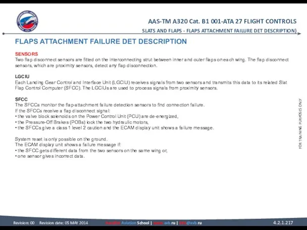
FLAPS ATTACHMENT FAILURE DET DESCRIPTION
SENSORS
Two flap disconnect sensors are fitted on
FLAPS ATTACHMENT FAILURE DET DESCRIPTION SENSORS Two flap disconnect sensors are fitted on
SLATS AND FLAPS - FLAPS ATTACHMENT FAILURE DET DESCRIPTION)
SENSORS - LGCIU
SLATS AND FLAPS - FLAPS ATTACHMENT FAILURE DET DESCRIPTION)
SENSORS - LGCIU
SFCC CONTROL INTERFACES
CSU
The Command Sensor Unit (CSU) sends two discrete signals
SFCC CONTROL INTERFACES CSU The Command Sensor Unit (CSU) sends two discrete signals
SLATS AND FLAPS - SFCC CONTROL INTERFACES
CSU - CFDIU
SLATS AND FLAPS - SFCC CONTROL INTERFACES
CSU - CFDIU
SFCC MONITOR INTERFACES
FWC
The Instrumentation Position Pick-off Units (IPPUs) supply slat/flap
SFCC MONITOR INTERFACES FWC The Instrumentation Position Pick-off Units (IPPUs) supply slat/flap
ADIRU
Flap position data are used by the Air Data/Inertial Reference Units
ADIRU Flap position data are used by the Air Data/Inertial Reference Units
FWC - EIU
SLATS AND FLAPS - SFCC MONITOR INTERFACES
FWC - EIU
SLATS AND FLAPS - SFCC MONITOR INTERFACES
FLIGHT CONTROLS SYSTEM LINE MAINTENANCE
DAILY CHECK
During the daily check, the external
FLIGHT CONTROLS SYSTEM LINE MAINTENANCE DAILY CHECK During the daily check, the external

SLATS AND FLAPS - FLIGHT CONTROLS SYSTEM LINE MAINTENANCE
DAILY CHECK
SLATS AND FLAPS - FLIGHT CONTROLS SYSTEM LINE MAINTENANCE
DAILY CHECK
FLIGHT CONTROLS SYSTEM LINE MAINTENANCE
MEL/DEACTIVATION
AILERONS
As aileron servocontrol is a MMEL
FLIGHT CONTROLS SYSTEM LINE MAINTENANCE MEL/DEACTIVATION AILERONS As aileron servocontrol is a MMEL
SLATS AND FLAPS - FLIGHT CONTROLS SYSTEM LINE MAINTENANCE
MEL/DEACTIVATION - AILERONS
SLATS AND FLAPS - FLIGHT CONTROLS SYSTEM LINE MAINTENANCE
MEL/DEACTIVATION - AILERONS
FLIGHT CONTROLS SYSTEM LINE MAINTENANCE
MEL/DEACTIVATION (continued)
ELEVATORS
The elevator servocontrol position transducer (XDCR)
FLIGHT CONTROLS SYSTEM LINE MAINTENANCE MEL/DEACTIVATION (continued) ELEVATORS The elevator servocontrol position transducer (XDCR)
SLATS AND FLAPS - FLIGHT CONTROLS SYSTEM LINE MAINTENANCE
MEL/DEACTIVATION - ELEVATORS
SLATS AND FLAPS - FLIGHT CONTROLS SYSTEM LINE MAINTENANCE
MEL/DEACTIVATION - ELEVATORS
FLIGHT CONTROLS SYSTEM LINE MAINTENANCE
MEL/DEACTIVATION (continued)
ELAC
There are two ELACs (ELAC 1
FLIGHT CONTROLS SYSTEM LINE MAINTENANCE MEL/DEACTIVATION (continued) ELAC There are two ELACs (ELAC 1
SLATS AND FLAPS - FLIGHT CONTROLS SYSTEM LINE MAINTENANCE
MEL/DEACTIVATION - ELAC
SLATS AND FLAPS - FLIGHT CONTROLS SYSTEM LINE MAINTENANCE
MEL/DEACTIVATION - ELAC
FLIGHT CONTROLS SYSTEM LINE MAINTENANCE
MEL/DEACTIVATION (continued)
WTB
On SLAT or FLAP WTBs, one
FLIGHT CONTROLS SYSTEM LINE MAINTENANCE MEL/DEACTIVATION (continued) WTB On SLAT or FLAP WTBs, one
SLATS AND FLAPS - FLIGHT CONTROLS SYSTEM LINE MAINTENANCE
MEL/DEACTIVATION - WTB
SLATS AND FLAPS - FLIGHT CONTROLS SYSTEM LINE MAINTENANCE
MEL/DEACTIVATION - WTB
FLIGHT CONTROLS SYSTEM LINE MAINTENANCE
MAINTENANCE TIPS
IMPROVE FLIGHT CONTROL SYSTEM TROUBLE SHOOTING
FLIGHT CONTROLS SYSTEM LINE MAINTENANCE MAINTENANCE TIPS IMPROVE FLIGHT CONTROL SYSTEM TROUBLE SHOOTING
MAINTENANCE TIPS
IMPROVE FLIGHT CONTROL SYSTEM TROUBLE SHOOTING AND MINIMIZE NO FAULT
MAINTENANCE TIPS IMPROVE FLIGHT CONTROL SYSTEM TROUBLE SHOOTING AND MINIMIZE NO FAULT
SLATS AND FLAPS - FLIGHT CONTROLS SYSTEM LINE MAINTENANCE
MAINTENANCE TIPS -
SLATS AND FLAPS - FLIGHT CONTROLS SYSTEM LINE MAINTENANCE
MAINTENANCE TIPS -
FLIGHT CONTROLS SYSTEM LINE MAINTENANCE
MAINTENANCE TIPS (continued)
ELEVATOR SERVOCONTROL SWAPPING TOOL (BUNDLE)
When
FLIGHT CONTROLS SYSTEM LINE MAINTENANCE MAINTENANCE TIPS (continued) ELEVATOR SERVOCONTROL SWAPPING TOOL (BUNDLE) When
SLATS AND FLAPS - FLIGHT CONTROLS SYSTEM LINE MAINTENANCE
MAINTENANCE TIPS -
SLATS AND FLAPS - FLIGHT CONTROLS SYSTEM LINE MAINTENANCE
MAINTENANCE TIPS -
FLIGHT CONTROLS SYSTEM LINE MAINTENANCE
MAINTENANCE TIPS (continued)
EXTENSION
To be unlocked, the servo
FLIGHT CONTROLS SYSTEM LINE MAINTENANCE MAINTENANCE TIPS (continued) EXTENSION To be unlocked, the servo
SLATS AND FLAPS - FLIGHT CONTROLS SYSTEM LINE MAINTENANCE
MAINTENANCE TIPS -
SLATS AND FLAPS - FLIGHT CONTROLS SYSTEM LINE MAINTENANCE
MAINTENANCE TIPS -
FLIGHT CONTROLS SYSTEM LINE MAINTENANCE
MAINTENANCE TIPS (continued)
SAFETY COLLAR INSTALLATION
Once the maintenance-unlocking
FLIGHT CONTROLS SYSTEM LINE MAINTENANCE MAINTENANCE TIPS (continued) SAFETY COLLAR INSTALLATION Once the maintenance-unlocking
SLATS AND FLAPS - FLIGHT CONTROLS SYSTEM LINE MAINTENANCE
MAINTENANCE TIPS -
SLATS AND FLAPS - FLIGHT CONTROLS SYSTEM LINE MAINTENANCE
MAINTENANCE TIPS -
FLIGHT CONTROLS SYSTEM LINE MAINTENANCE
MAINTENANCE TIPS (continued)
RETRACTION
To retract the spoiler, the
FLIGHT CONTROLS SYSTEM LINE MAINTENANCE MAINTENANCE TIPS (continued) RETRACTION To retract the spoiler, the
 Преддипломная практика
 Аттестационная работа. Требования к исследовательской работе
 ЗНО 2016, 2017
 Конституционно-правовые основы российского государства для студентов очно-заочной формы обучения
 Аттестационная работа. Исследовательская и проектная деятельности учащихся: сходства и различия
 Nporpamma no gh^hnnhhe
 Анализ программно-методического обеспечения программы: От рождения до школы
 Учебная практика. Проектная практика
 Марийский государственный университет. Юридический факультет
 Государственный менеджмент
 Несовершенство инновационных технологий в высших учебных заведениях
 Отчет по преддипломной практике на предприятии ОАО РУСПОЛИМЕТ
 Аттестационная работа. Исследовательская деятельность на уроках математики
 Вступ 2016: Умови прийому та вступна компанія
 Грантовая поддержка
 Аттестационная работа. Образовательная программа внеурочной деятельности. Учусь создавать проект
 Аттестационная работа. Выбор как средство формирования учащимися собственной индивидуальной траектории обучения
 Аттестационная работа. Проектно-исследовательская деятельность младших школьников
 О мониторинге работы школьных спортивных клубов в общеобразовательных учреждениях Белгородской области
 Новые правовые и практические аспекты проведения аттестации педагогических работников
 Курсовая работа
 Открытый районный межшкольный литературно-краеведческий турнир БОЛЬШАЯ ИГРА
 Аттестационная работа. Проектная и исследовательская деятельность как способ формирования метапредметных результатов обучения
 Профориентационное тестирование учащихся 9, 11 классов в рамках акции Выпускник
 Coursera. Проект в помощь обучающимся
 Аттестационная работа. Внеурочная деятельность по ФГОС в ГБОУ РО Каменск-Шахтинская школа-интернат. (1-6 класс)
 Особенности поступления в 2022 году. ИГУ
 Профессия - библиотекарь