- Rubicon. System manual block mounter

Содержание
- 2. Regarding the any case of accident and incidents occurred by customer’s program modification or parts change
- 3. * Notice for Safety*
- 4. This manual is including information related to secure the safety. Please be fully aware of this
- 5. 1. Machine Specification
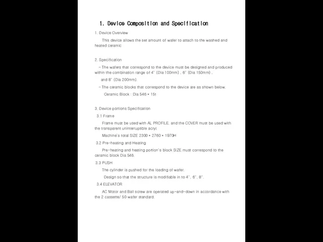
- 6. 1. Device Composition and Specification 1. Device Overview This device allows the set amount of wafer
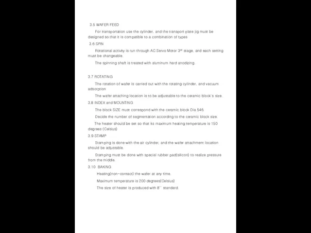
- 7. 3.5 WAFER FEED For transportation use the cylinder, and the transport plate jig must be designed
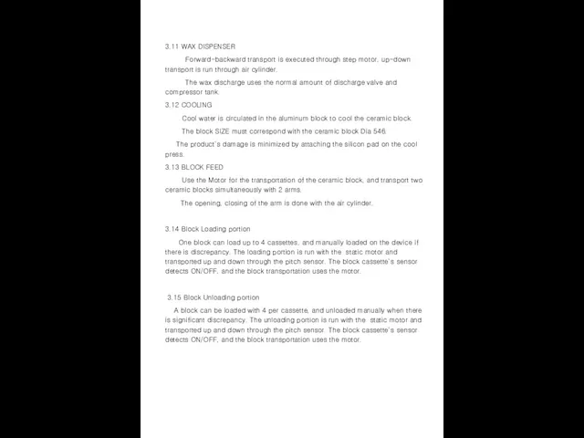
- 8. 3.11 WAX DISPENSER Forward-backward transport is executed through step motor, up-down transport is run through air
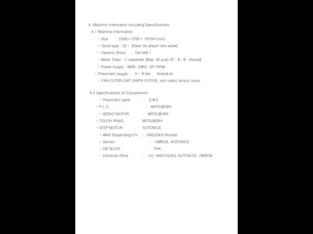
- 9. 4. Machine Information including Specifications 4.1 Machine Information - Size : 2300 * 2760 * 1970H
- 10. 2. OPREATION BOARD
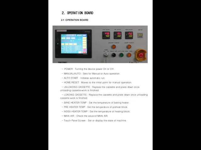
- 11. 2-1 OPERATION BOARD 2. OPERATION BOARD - POWER : Turning the device power On or Off
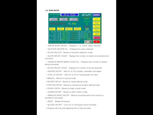
- 12. 2-2 MAIN MODE - WAFER WORK SELECT : Displays 4”, 6” and 8” wafer selected. -
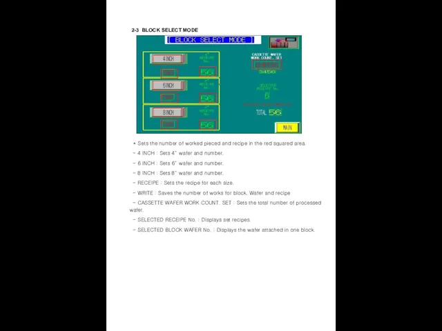
- 13. 2-3 BLOCK SELECT MODE * Sets the number of worked pieced and recipe in the red
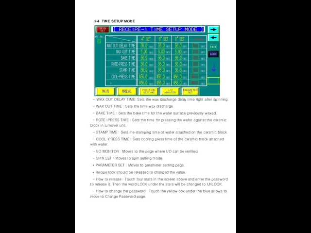
- 14. 2-4 TIME SETUP MODE - WAX OUT DELAY TIME: Sets the wax discharge delay time right
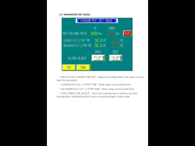
- 15. 2-5 PARAMETER SET MODE - HEFA FILTER CHANGE TIME SET : Replace the Hepa-filter once alarm
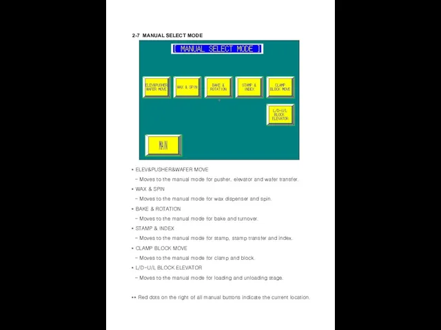
- 16. 2-7 MANUAL SELECT MODE * ELEV&PUSHER&WAFER MOVE - Moves to the manual mode for pusher, elevator
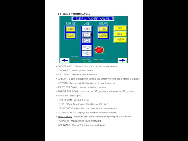
- 17. 2-8 ELEV & PUSHER MANUAL * PUSHER ASSY : Pushed the stacked wafer in the cassette.
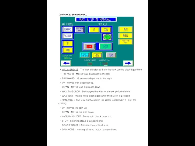
- 18. 2-9 WAX & SPIN MANUAL * WAX DISPENSE : The wax transferred from the tank can
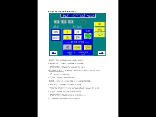
- 19. 2-10 BAKE & ROTATION MANUAL * BAKE : Wax coated wafer can be baked. - FORWARD
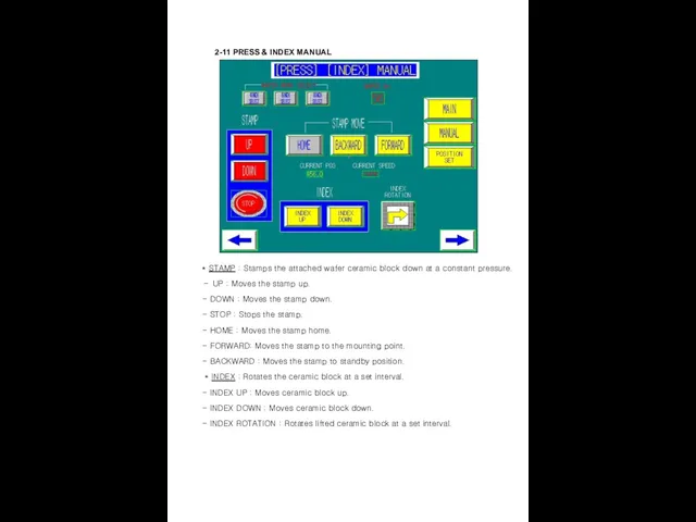
- 20. 2-11 PRESS & INDEX MANUAL * STAMP : Stamps the attached wafer ceramic block down at
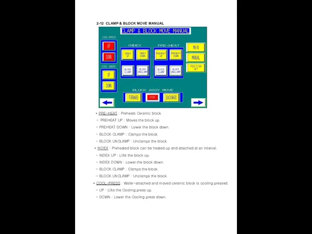
- 21. 2-12 CLAMP & BLOCK MOVE MANUAL * PRE-HEAT : Preheats Ceramic block. - PREHEAT UP :
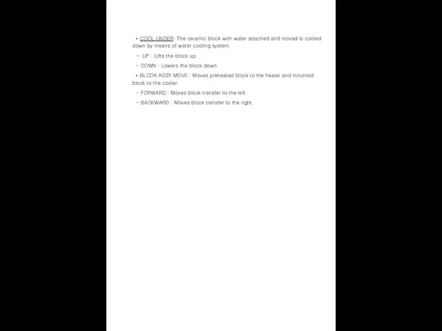
- 22. * COOL UNDER: The ceramic block with wafer attached and moved is cooled down by means
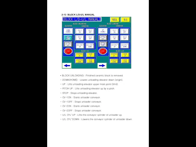
- 23. 2-13 BLOCK L/D-U/L MANUAL * BLOCK UNLOADING : Finished ceramic block is removed. - DOWN(HOME) :
- 24. * BLOCK LODING : The new ceramic block is inserted here. - UP(HOME) : Lifts loading
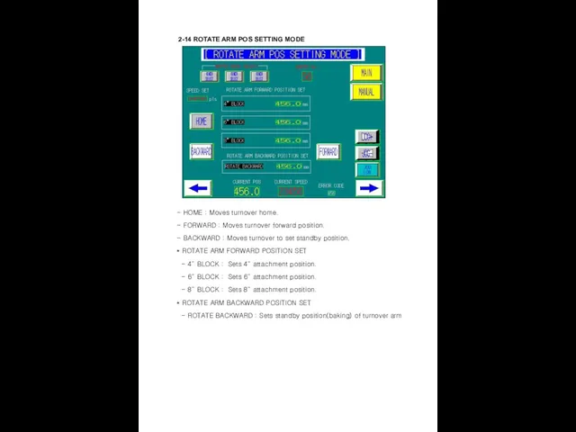
- 25. 2-14 ROTATE ARM POS SETTING MODE - HOME : Moves turnover home. - FORWARD : Moves
- 26. 2-15 STAMP PRESS POS SETTING MODE - PRESS HOME : Moves stamp home. - STAMP POS
- 27. 2-16 INDEX POS SETTING MODE - INDEX SPEED SET : Sets index speed. - : Rotates
- 28. 2-17 WAX ARM POS SETTING MODE - 4” FORWARD POS : Sets forward position and velocity
- 29. 2-18 ELEV POS SETTING MODE - ELEV HOME : Moves elevator home. - 1SLOT POS DOWN
- 30. 2-19 SPIN SET MODE - HOME : Performs homing of servo driver for spin. - 1CYCLE
- 31. 2-20 ALARM HISTORY MODE - Displays the history of alarm (Date and Time) - Can delete
- 32. 2-21 RECEIPE & POS PASSWORD - Touch number box of screen allows to change the password.
- 33. 2-22 POSITION MODE PASSWARD INPUT - Entering position setting mode requires password Touch four yellow stars
- 34. 2-23 INPUT MONITOR Displays INPUT content and ON/OFF Condition
- 35. 2-24 OUPUT MONITOR Displays OUTPUT content and ON/OFF Condition.
- 36. 2-25 ALARM * Mark the respective alarm contents on the main mode. - BZ ON/OFF :
- 37. * STAMP(AXIS3) POS UNIT ERROR - Check the stepping motor error that drives the stamp’s forward-backward
- 38. * ROTATE ASSY CY UP TIME OVER - Alarm generated due to the excess of time
- 39. * STAMP PRESS DOWN TIME OVER - Alarm generated due to the excess of time elapsed
- 40. * BAKE CY FRW TIME OVER - Alarm generated due to the excess of time elapsed
- 41. * BLOCK U/L INV#3 ERROR - Error from the loading portion motor. Turn off the device
- 42. * CASSETTE WAFER LOT WORK FINISH - Alarm generated after all work is complete. Remove the
- 43. * LD DOOR DOWN TIME OVER Alarm that is generated when the loading portion cassette of
- 44. *** If there is a TIME OVER alarm set off, check the air supply status, and
- 45. 3. Preparation of Operation
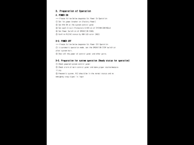
- 46. 3. Preparation of Operation A. POWER ON *** Please follow below sequence for Power On Operation
- 47. 4. Manual Operation
- 48. 4. Manual Operation 4-1.Condition of Manual Operation ◆ Switch to operation preparation status following sequence ◆
- 49. 5. Automatic Operation
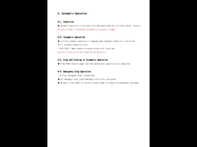
- 50. 5. Automatic Operation 5-1. Condition ◆ Automatic Operation is available only when whole machine is at
- 51. 6. MAINTENANCE
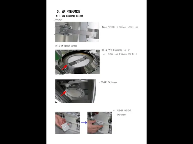
- 52. 6. MAINTENANCE 6-1. Jig Exchange method PUSHER - Move PUSHER to oriianl postition 2) SPIN CHUCK
- 53. 6-2. WAX TANK, DISPENSING VALVE * WAX TANK - MODEL : JB03-LRG - Recommended Air Pressure
- 54. 6-3. Regulator 1) STAMP - Usage Pressure 4 INCH : 0.03 Mpa 6 INCH : 0.04
- 55. 6-4. HEATER / VACUUM / BLOCK TEMP. 1) OPERATE PANEL HEATER SETTING - BAKE HEATER :
- 56. 6-5. BAKE HEATER / STAMP gap setting 1) BAKE HEATER SETTING - Secure about 1~2mm gap
- 57. 6-6. MAINTENANCE LIST.
- 58. 7. PLC PROGRAM
- 59. 8. PLC I/O
- 60. 9. Electric Circuit Drawing
- 61. 10. Overall Assembly Drawing
- 62. 11. Partial Assembly Drawing (Including Parts List)
- 64. Скачать презентацию
Regarding the any case of accident and incidents occurred by customer’s
* Notice for Safety*
* Notice for Safety*
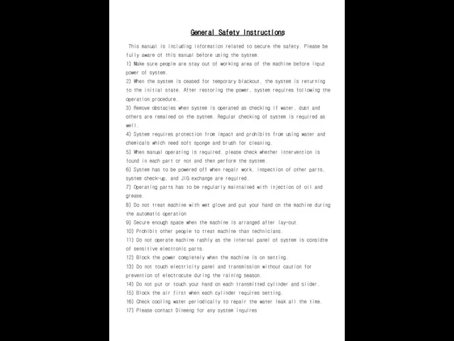
This manual is including information related to secure the safety.
This manual is including information related to secure the safety.
1. Machine Specification
1. Machine Specification
1. Device Composition and Specification
1. Device Overview
This
1. Device Composition and Specification
1. Device Overview
This
3.5 WAFER FEED
For transportation use the cylinder, and the transport
3.5 WAFER FEED
For transportation use the cylinder, and the transport
3.11 WAX DISPENSER
Forward-backward transport is executed through step motor, up-down
3.11 WAX DISPENSER
Forward-backward transport is executed through step motor, up-down
4. Machine Information including Specifications
4.1 Machine Information
- Size
4. Machine Information including Specifications
4.1 Machine Information
- Size
2. OPREATION BOARD
2. OPREATION BOARD
2-1 OPERATION BOARD
2. OPERATION BOARD
- POWER : Turning the
2-1 OPERATION BOARD
2. OPERATION BOARD
- POWER : Turning the
2-2 MAIN MODE
- WAFER WORK SELECT : Displays 4”, 6”
2-2 MAIN MODE
- WAFER WORK SELECT : Displays 4”, 6”
2-3 BLOCK SELECT MODE
* Sets the number of worked
2-3 BLOCK SELECT MODE
* Sets the number of worked
2-4 TIME SETUP MODE
- WAX OUT DELAY TIME: Sets the
2-4 TIME SETUP MODE
- WAX OUT DELAY TIME: Sets the
2-5 PARAMETER SET MODE
- HEFA FILTER CHANGE TIME SET
2-5 PARAMETER SET MODE
- HEFA FILTER CHANGE TIME SET
2-7 MANUAL SELECT MODE
* ELEV&PUSHER&WAFER MOVE
- Moves to
2-7 MANUAL SELECT MODE
* ELEV&PUSHER&WAFER MOVE
- Moves to
2-8 ELEV & PUSHER MANUAL
* PUSHER ASSY : Pushed
2-8 ELEV & PUSHER MANUAL
* PUSHER ASSY : Pushed
2-9 WAX & SPIN MANUAL
* WAX DISPENSE :
2-9 WAX & SPIN MANUAL
* WAX DISPENSE :
2-10 BAKE & ROTATION MANUAL
* BAKE : Wax
2-10 BAKE & ROTATION MANUAL
* BAKE : Wax
2-11 PRESS & INDEX MANUAL
* STAMP : Stamps
2-11 PRESS & INDEX MANUAL
* STAMP : Stamps
2-12 CLAMP & BLOCK MOVE MANUAL
* PRE-HEAT : Preheats
2-12 CLAMP & BLOCK MOVE MANUAL
* PRE-HEAT : Preheats
* COOL UNDER: The ceramic block with wafer attached and
* COOL UNDER: The ceramic block with wafer attached and
2-13 BLOCK L/D-U/L MANUAL
* BLOCK UNLOADING : Finished ceramic
2-13 BLOCK L/D-U/L MANUAL
* BLOCK UNLOADING : Finished ceramic
* BLOCK LODING : The new ceramic block is inserted here.
* BLOCK LODING : The new ceramic block is inserted here.
2-14 ROTATE ARM POS SETTING MODE
- HOME : Moves
2-14 ROTATE ARM POS SETTING MODE
- HOME : Moves
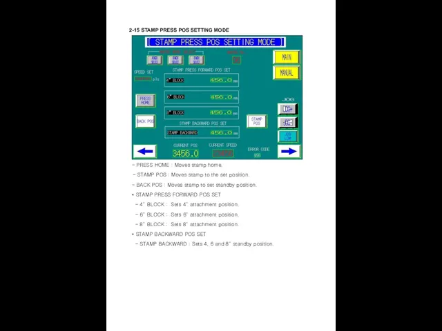
2-15 STAMP PRESS POS SETTING MODE
- PRESS HOME :
2-15 STAMP PRESS POS SETTING MODE
- PRESS HOME :
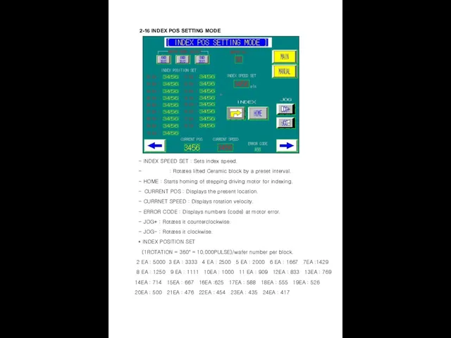
2-16 INDEX POS SETTING MODE
- INDEX SPEED SET :
2-16 INDEX POS SETTING MODE
- INDEX SPEED SET :
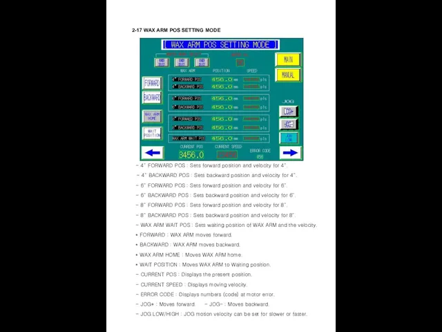
2-17 WAX ARM POS SETTING MODE
- 4” FORWARD
2-17 WAX ARM POS SETTING MODE
- 4” FORWARD
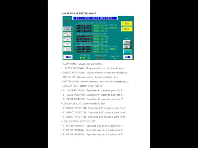
2-18 ELEV POS SETTING MODE
- ELEV HOME : Moves elevator
2-18 ELEV POS SETTING MODE
- ELEV HOME : Moves elevator
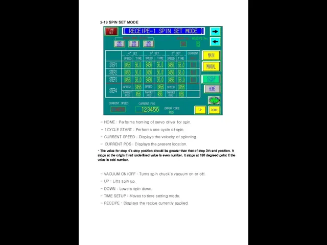
2-19 SPIN SET MODE
- HOME : Performs homing of
2-19 SPIN SET MODE
- HOME : Performs homing of
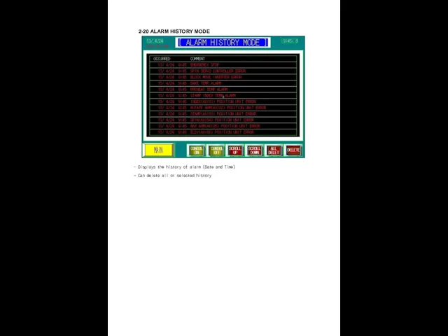
2-20 ALARM HISTORY MODE
- Displays the history of alarm (Date
2-20 ALARM HISTORY MODE
- Displays the history of alarm (Date
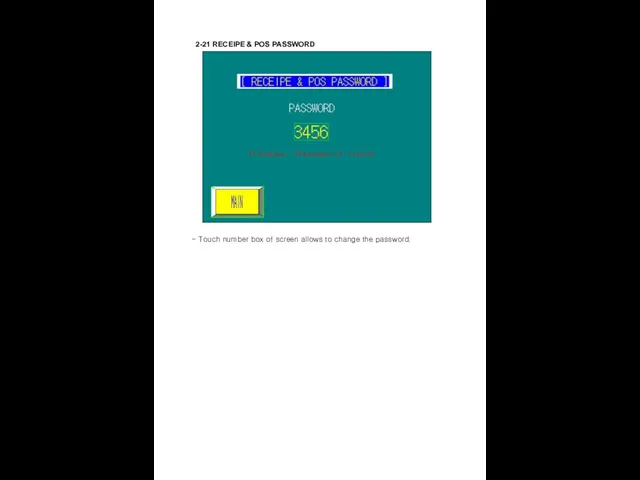
2-21 RECEIPE & POS PASSWORD
- Touch number box of screen
2-21 RECEIPE & POS PASSWORD
- Touch number box of screen
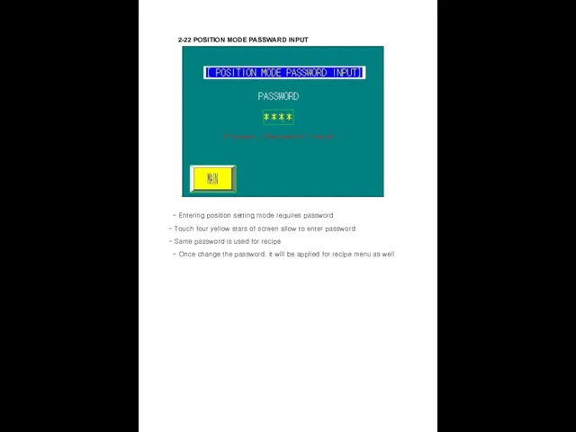
2-22 POSITION MODE PASSWARD INPUT
- Entering position setting mode requires
2-22 POSITION MODE PASSWARD INPUT
- Entering position setting mode requires
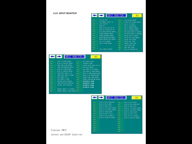
2-23 INPUT MONITOR
Displays INPUT
content and ON/OFF Condition
2-23 INPUT MONITOR
Displays INPUT
content and ON/OFF Condition
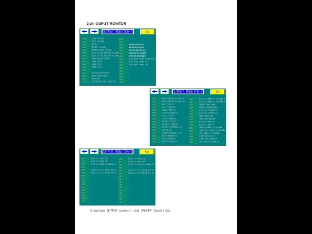
2-24 OUPUT MONITOR
Displays OUTPUT content and ON/OFF Condition.
2-24 OUPUT MONITOR
Displays OUTPUT content and ON/OFF Condition.
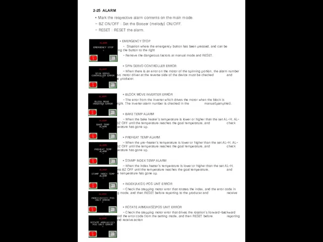
2-25 ALARM
* Mark the respective alarm contents on
2-25 ALARM
* Mark the respective alarm contents on

* STAMP(AXIS3) POS UNIT ERROR
- Check the stepping
* STAMP(AXIS3) POS UNIT ERROR
- Check the stepping

* ROTATE ASSY CY UP TIME OVER
- Alarm generated
* ROTATE ASSY CY UP TIME OVER
- Alarm generated

* STAMP PRESS DOWN TIME OVER
- Alarm generated due
* STAMP PRESS DOWN TIME OVER
- Alarm generated due

* BAKE CY FRW TIME OVER
- Alarm generated due
* BAKE CY FRW TIME OVER
- Alarm generated due

* BLOCK U/L INV#3 ERROR
- Error from the loading
* BLOCK U/L INV#3 ERROR
- Error from the loading
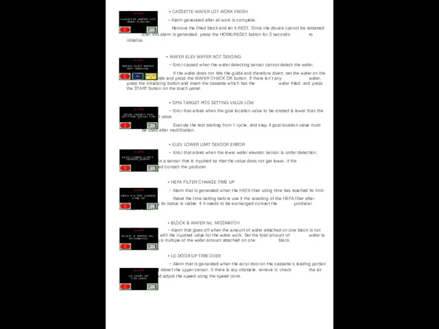
* CASSETTE WAFER LOT WORK FINISH
- Alarm generated after
* CASSETTE WAFER LOT WORK FINISH
- Alarm generated after

* LD DOOR DOWN TIME OVER
Alarm that is generated
* LD DOOR DOWN TIME OVER
Alarm that is generated
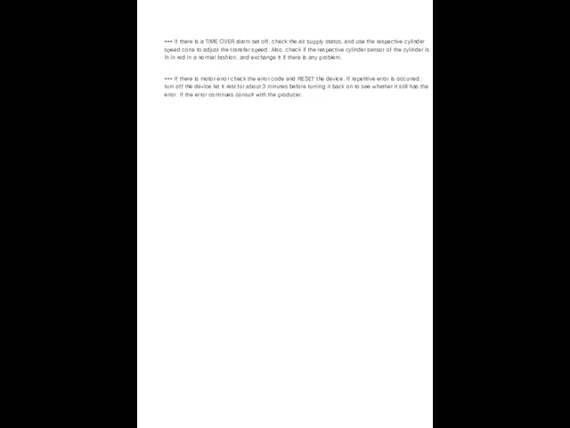
*** If there is a TIME OVER alarm set off, check
*** If there is a TIME OVER alarm set off, check

3. Preparation of Operation
3. Preparation of Operation
3. Preparation of Operation
A. POWER ON
*** Please follow below sequence for
3. Preparation of Operation
A. POWER ON
*** Please follow below sequence for
4. Manual Operation
4. Manual Operation
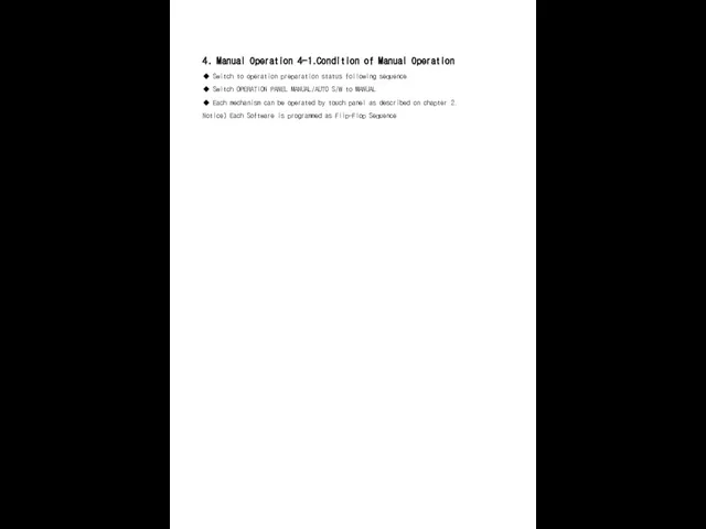
4. Manual Operation 4-1.Condition of Manual Operation
◆ Switch to operation
4. Manual Operation 4-1.Condition of Manual Operation
◆ Switch to operation
5. Automatic Operation
5. Automatic Operation
5. Automatic Operation
5-1. Condition
◆ Automatic Operation is available only
5-1. Condition
◆ Automatic Operation is available only
6. MAINTENANCE
6. MAINTENANCE
6. MAINTENANCE
6-1. Jig Exchange method
PUSHER
- Move PUSHER to
6. MAINTENANCE
6-1. Jig Exchange method
PUSHER
- Move PUSHER to
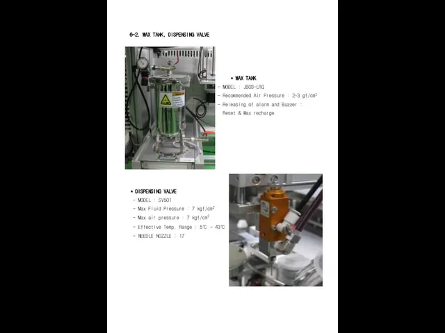
6-2. WAX TANK, DISPENSING VALVE
* WAX TANK
- MODEL
6-2. WAX TANK, DISPENSING VALVE
* WAX TANK
- MODEL
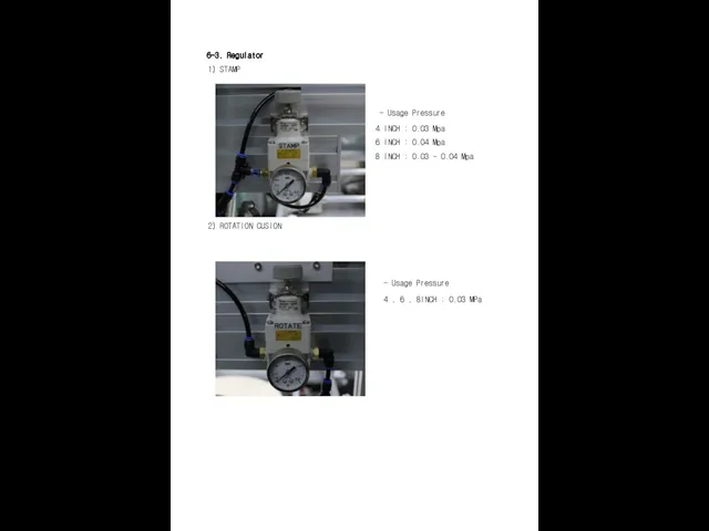
6-3. Regulator
1) STAMP
- Usage Pressure
4 INCH :
6-3. Regulator
1) STAMP
- Usage Pressure
4 INCH :
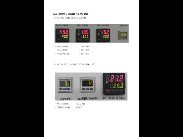
6-4. HEATER / VACUUM / BLOCK TEMP.
1) OPERATE
6-4. HEATER / VACUUM / BLOCK TEMP.
1) OPERATE
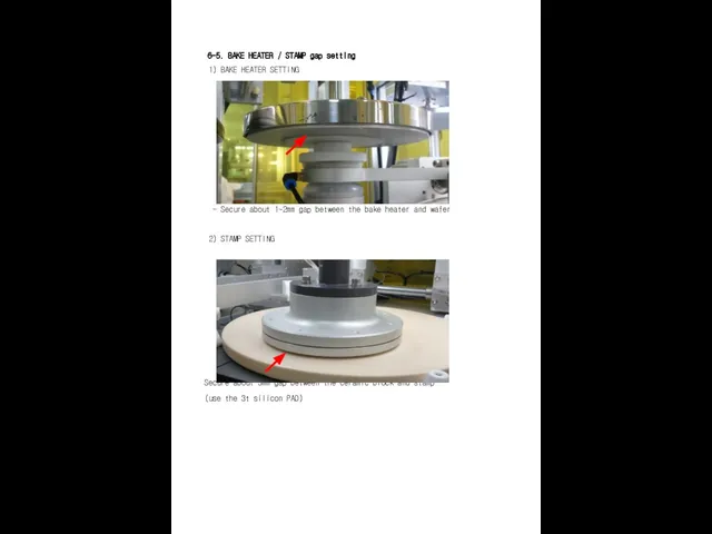
6-5. BAKE HEATER / STAMP gap setting
1) BAKE
6-5. BAKE HEATER / STAMP gap setting
1) BAKE
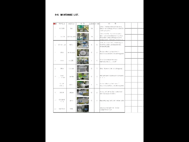
6-6. MAINTENANCE LIST.
6-6. MAINTENANCE LIST.
7. PLC PROGRAM
7. PLC PROGRAM

8. PLC I/O
8. PLC I/O
9. Electric Circuit Drawing
9. Electric Circuit Drawing
10. Overall Assembly Drawing
10. Overall Assembly Drawing
11. Partial Assembly Drawing (Including Parts List)
11. Partial Assembly Drawing (Including Parts List)
 Конструкция кормовой части корабля
 Водородный транспорт
 volkova_ebnacproekty_i_reshaem_vmeste_2022
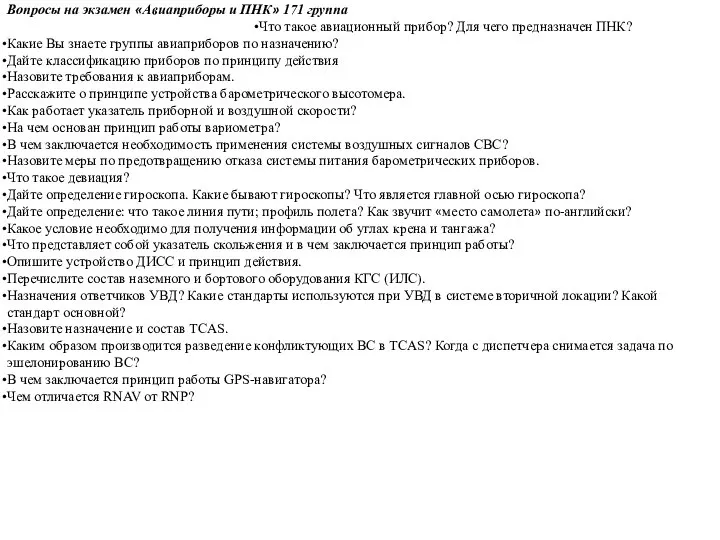 Вопросы на экзамен Авиаприборы и ПНК
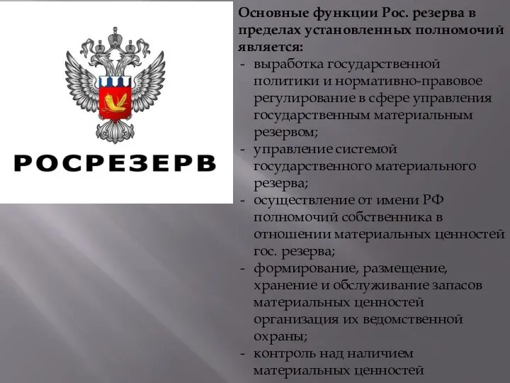 Основные функции Рос. резерва в пределах установленных полномочий является
 Веселая азбука П
 Основы проектирования и строительства железных дорог
 Пищеварение в ротовой полости
 Популярные косметические процедуры
 Борьба с зимней скользкостью
 Етістіктің түрленуі. Шақ туралы түсінік
 Закрытое акционерное общество Тольяттинский завод автоагрегатов. Гарантии
 Оборудование пассажирского вагона. Упругие переходные площадки
 Защита Андрощука Бориса
 щелкун
 Типология объектов жилой недвижимости
 Развитие изобразительных способностей старших дошкольников в процессе ознакомления с творчеством художников-иллюстраторов
 Союзы
Союзы F-F4
F-F4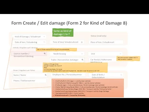 Form Create / Edit damage (Form 2 for Kind of Damage 8)
 Prezentatsia
 Изделия из дерева и металла
 Яхнин Леонид Львович
 Иные языки
 Дифракция звука на цилиндре, окруженном неоднородным жидким слоем
 Prezentatsia1
 Словарь в картинках (а-и)
 Закладки из картона и бумаги